Flexing Your Muscle: Hydraulic Systems in Excavators and Earthmoving Equipment
The Greek philosopher Archimedes once said, “Give me a place to stand, and I can move the world.” He was talking about leverage, but the same force multiplying principle applies to hydraulics. Simply put, hydraulics is a way to multiply force by utilizing an incompressible fluid (typically oil). The initial force is applied at one end of the hydraulic system, transmitted through the fluid, with constant pressure to the other end.
For example, a force of 10 pounds applied to one end of a system by a piston (fitted into what is referred to as the “master cylinder”) with a 1-square-foot cross sectional area resulting in an applied pressure of 10 pounds per square foot. At the other end of the hydraulic system, the cross sectional area of the receiving piston (set within the “slave” cylinder) is 10 square feet. The transmitted pressure of 10 pounds per square foot therefore becomes a force of 100 pounds.
The piping connecting the two pistons can be of any shape, configuration, or length due to the incompressible nature of the hydraulic oil. Furthermore, one master cylinder can apply force to any number of slave cylinders. This simple system is also very efficient. Again, due to the incompressible nature of the oil, almost all of the applied force from the master cylinder acts on the slave cylinder.
The tradeoff between the master and slave cylinder is between the distance of movement and the applied force. This is known as “hydraulic multiplication.” In our example, the resultant force on the slave cylinder is 10 times greater than the applied force created by the master cylinder due to the slave cylinder’s greater surface area. But the slave cylinder’s piston will move only 1 foot for every 10 feet that the master cylinder’s piston moves.
Lever arms and block and tackles operate on the same mechanical principles. So one garage repairman working a hydraulic lever can generate enough force to lift a large car on a rack well above his head. Brakes on a passenger car operate the same way to multiply the force of the driver’s foot pressure to apply enough force to the brake systems master cylinder to transmit enough force to the slave cylinders at each wheel’s brake pad to slow or stop a heavy car moving at high speed.
Mechanical hydraulic systems utilized by vehicles and equipment are connected by a series of valves and piping to a pump that supplies high pressure oil. It is vitally important that these connections retain their tight seals. Seal integrity is not just important for preventing the loss of hydraulic fluid; it is also important to prevent the entrainment of air bubbles in the fluid itself. Unlike hydraulic oil, air is compressible. So if a bubble is trapped within the system transmission lines, the force generated on the system will go towards compressing the air bubble instead of being directly applied to the slave cylinder. This greatly reduces the effective force and overall efficiency of the system, often to unsafe levels. This is why brakes can fall “mushy” and why a car mechanic will “bleed” the air out of a hydraulic brake line to restore its proper performance.
Hydraulics and Heavy Equipment Operations
Hydraulic equipment applies the scientific principles described above in order to perform useful work via multiple machine functions: Engines and motors operate a pump, these pumps pressurize the hydraulic fluid (mineral oil polyalphaolefin or organophosphate ester), the fluid travels through hydraulic tubes to actuators, and the actuators drive the arm or bucket doing the excavation. The fluid is recycled through the system, passing through filters on the way back to the pump.
The above description is somewhat over simplified. An actual hydraulic system requires a wide range and variety of valves, pumps, filters check valves, counterbalance valves, hydraulic cylinders, pump filters, tubes, and seals capable of withstanding high pressures. In fact, all the materials (metals, steel and stainless steel alloys, bras, woven wire, and synthetics) used to make a hydraulic system must be extremely strong and durable. At the top of this list is titanium, often used in extreme high-pressure systems operating at more than 50,000 psi.
Crawler excavators are mobile work machines with at least six hydraulic actuators: boom, lift arm, bucket (all three for equipment), swing, travel left, and travel right. This diversity of working functions places special demands on its hydraulic system. During operations, a crawler excavator’s hydraulic system may be required to conduct all movements smoothly, simultaneously, sensitively, and independently. High-volume flows of hydraulic fluids will be required to ensure fast movements during excavation. This is achieved with differential cylinders, whose hydraulic flow raters are twice the installed pump volume.
An excavator’s drive system should convert 100% of the engine output hydraulically. And its hydrostatic power will be much higher than the maximum engine output. Each movement’s volume flow is optimized; due to economic reasons, the number of pump circuits is limited, so this movement optimization is achieved by combining or separating pump circuits. For that purpose, independent movement is achieved by tuning the hydraulic flows by means of control valves, although more advanced systems utilize and software and sensor technology. It is the newer hydraulic control systems that are using intelligent electric systems and electronics.
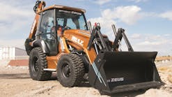
Other earthmoving equipment utilize different hydraulic system configurations. A skid loader and front end loaders (which are more of bulk material handlers than a true excavator) also depends on hydraulics. Its large front end bucket requires three pairs of hydraulic pistons for operation: one pair that raises and lowers the bucket, another pair that vertically tilts and rotates the bucket to allow loading and dumping, and a last pair that can split the bucket to allow it to grab objects like steel I-beams or logs.
Dump trucks also use hydraulics, though in a much simpler configuration. Depending on the make and model, dump trucks have either one or two large hydraulic cylinders to raise and lower the truck bed. These hydraulic cylinders have two unique design futures. First, they telescope in multiple segments to allow for a long movement length, and they tend to be more powerful in order to lift the heavy load of a fully loaded dump.
Heavy Equipment and the Types of Hydraulic Systems They Utilize
Hydraulics allow excavators to perform their many functions. These machines are not just limited to earthwork. They also lift and place heavy objects such as sewer pipes, equipment, building panels, etc. Their hydraulic systems function within the overall parameters of the machine’s performance (weight, center of gravity, lift point, reach, tractor tread footprint, etc.)
These design dimensions determine the excavator’s tipping point (the point where the load carried by the excavator bucket and the position of the bucket in relation to the excavator’s center of gravity causes the end rollers to lift away from the track rails). Mathematically, the tipping point is the load located at a particular radius. Similarly, the excavator’s rating height is defined by its load, and the vertical distance from the bucket to the ground.
The excavator’s overall lifting capacity is determined by its tipping point and its hydraulic capacity. Hydraulic lifting capacity can also be altered by equipment configuration. Utilizing the Society of American Engineers (SAE) guidelines for equipment design, loads, and geometry, an excavator’s maximum lifting capabilities can be determined.
However, the position of the load can be more complicated than the location of the bucket itself. For example, loads can be suspended from an excavator bucket by means of straps or chains, not just the load of earth within the bucket itself. The geometry and weight of these suspended loads must also be factored into the equipment’s tipping point.
In order to ensure against tipping failures, the rated hoist loads are established at weights and distances less than the actual tipping point. Usually, the rated load will not exceed 75% of the tipping load or 87% of the excavator’s hydraulic capacity. These limits establish a factor of safety against tipping of 1.15–1. As a practical matter, these limitations determine the techniques used to optimize operations and to ensure safe and efficient excavation. When excavating at ground level, keep the reach and cable short and close to the excavator’s body. When lifting or digging well below grade, lengthen the cable or reach to ensure that the bucket hinge is located in the optimum lifting location.
Long reach excavators are in a category all by themselves. They are used for light digging and lifting, requiring unusually long reach capability. Heavy lifting capacity and long reach cannot be combined in an economic and practical matter. Excavator design is a trade off between these two goals. So long reach excavators are usually used in cohesionless soil at significant depth, such as sand and gravel quarries. Long-reach excavators come with purpose built booms and sticks, linkage cylinders, hydraulic lines, heavy duty and ultra wide undercarriage, and additional counterweights opposite of the bucket location (to improve tipping stability).
All of these parameters come together to determine the mechanical specifications of an excavator. Take for example a typical medium sized excavator weighing almost 30 tons. It is equipped with a bucket having a 1.0–1.5 cubic yard capacity capable of lifting up to 1.5 tons. It can move with relative agility and precision across a work site. This moment is made possible by an 8.3-liter displacement diesel engine that can generate up to 350 horsepower. This engine drives a pair of pumps with up to 150 gallons per minute flow rate delivered at a pressure of 4,500 psi. The pumps hydraulic pistons have 5.5-inch diameter faces and 4-inch diameter shafts. Each shafts hydraulic motor can operate at 10–12 revolutions per minute (rpm). These hydraulic pumps are operated from the cab by a pair of joysticks and four pedals, which send electronic signals to eclectic valve blocks integrated with the pumps. These valve blocks in turn connect to the pistons by means of high-pressure hydraulic lines.
It isn’t just the bucket and arm that is operated by hydraulics. The excavator moves on tracks which are also hydraulically controlled. The tracks on any piece of earthmoving machinery are driven by hydraulic motors located at one end and a free spinning toothed wheel at the other. The first provides the driving force while the later ensure the track’s alignment and tension on the other rotors.
Where Is Hydraulics Technology Heading?
Hydraulics technology is more tortoise than hare. Instead of major leaps, it has advanced incrementally and steadily. The base architecture of many of the electro-hydraulic systems we use today have been around for at least 25 years. It’s not that hydraulics in general have taken a leap forward, but rather, they have continued advancing in the three main areas of the hydraulics control system. Joystick (input), actuator (output), and sensor (feedback) technology have matured to a very high level of reliability and cost effectiveness.
Yet, like compound interest, small improvements add up to big changes over time. The most notable changes can be simplified overall design of the hydraulic lines combined with more complicated electronics and computers. This is especially true in excavators, which are far more complicated than other earthmoving equipment. Excavators require more complicated controls to coordinate their movements and ensure efficient operation, and also simplicity of design to minimize maintenance and operating costs.
The effects of technological improvements on the human element should not be ignored. The advancement of hydraulics over the last 20 years or so can be first noticed by the operator in ease of operation. Reduction in operator fatigue and “ease of use” has been a large driver behind many of the advancements hydraulic systems use today. The first hydraulic system to accomplish both greater efficiency and greater ease of use was the pressure compensated load-sensing (PCLS) system. This reduced operator fatigue by making the balancing act of multi-function metering much easier. In the old days, balancing the speed of multi-functions was accomplished by a highly skilled operator. It was a juggling act to keep all the functions moving to make a flat trench or cut a level grade. The introduction of pressure compensation made the flow matching all internal to the valve. The operator still had to pick the right speed, so to say, but from there the speed would not change based on load.
As with all new technology, it can take time for the marketplace to accept it. Earthmoving companies are in business to make money, as are all businesses. The decision to adopt new technology is a business and financial system, not a scientific one. A new computer control system, for example, must justify its additional cost with improved productivity. In the case of hydraulic systems the two main drivers involved in gaining acceptance with any new technology are increased productivity and reduced fuel consumption. If these two goals are measurable and repeatable, the new technology becomes accepted. As such, an equipment salesman has to make the case to an owner/operator that a new technical improvement will positively affect the owner’s bottom line while making the operator job easier and safer.
Major Manufacturers and Innovators
CASE Construction excavators range in size from the miniature 16,000 pound/55 horsepower CX75C-SR to the monster 178,575 pound/532 horsepower CX800B. The CASE CX75C-SR operates with a minimum swing radius designed for working in more confined areas. With a 7% faster cycle time, it delivers 9% more hydraulic power than previous models. The CASE CX800B excavator achieves up to a 17% increase in horsepower from the CASE Tier-III certified Isuzu engine. Digging force is increased by 10% with the Auto Power Boost feature. Their Intelligent Hydraulic System (IHS) incorporates five energy saving features that contribute to a substantial cut in operating costs with an increase in productivity. The IHS operates from a single central processing unit for improved controllability and simplified diagnostics.
Caterpillar Inc. has seen more electro hydraulics being applied to their excavators in order to reduce fuel consumption and maintain the same power as older machines. In doing so, Caterpillar has met customer needs for better fuel consumption and efficiency without loss of performance. A major benefit of this approach is reduced noise levels due to lower engine rpm and increased main pump displacement that maintains the power from the prior series. Caterpillar has developed synergies among products where technology and components and principles are used on the excavators. Some are pilot systems and others are electro-hydraulic that improve hydraulic efficiencies. Their advances in efficiency have been achieved with no trade-offs in performance versus the prior model. Caterpillar has adopted “customer panels” that help to define the value they perceive to make their companies more profitable, and what critical requirements are needed to help them to advance in the future and provide a better return.
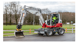
Exacavators are kings of the hydraulics machines
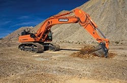
Doosan Infracore Construction Equipment America has emphasized advanced controls to go with their advanced hydraulics systems. Operators can chose from four different power modes to achieve improved control and fuel efficiency: Power+ mode delivers fast workgroup speeds for loading, along with extra power for digging in hard ground; power mode delivers provides high power for difficult digging conditions; standard power mode balances the excavator’s fuel consumption and production for typical digging operations; and economy mode reduces fuel consumption for low-demand applications by slowing down machine movement for conditions that require extra precision. In addition to power modes, Doosan excavators can chose between four work modes: Digging, Breaker, Shear, and Lifting. Switching work configurations is easily accomplished by adjusting a dial switch on the console.
“Some of the more technological advanced upgrades include an increase of integrated electronics, such as an electrical powered pump working with the engine control unit (ECU) on the machine,” says Shane Reardon, Doosan excavator product specialist. “The computers talk to each other and the owner can maximize his performance by matching the engine horsepower to the output of the hydraulic pump. Production rises and customers see significant fuel savings.” One of these new advancements is their Smart Power Control (SPC). This consists of two control systems—variable speed and pump torque. The ECU automatically manages SPC when SPC is engaged. SPC works with each of the four power modes and the digging work mode. Variable speed control reduces energy requirements by 5% by reducing engine rpm during low workload requirements such as during the swing portion of a dig cycle. Pump torque control matches hydraulic pump torque and engine response to the task, preventing engine overload and excess fuel consumption.
Hyundai Construction Equipment has pioneered the use of accumulators like those in their Hi-POSS excavator. Hi-POSS is an acronym for Hyundai Intelligent Power Optimal Sharing and Energy Saving. These accumulators can minimize hydraulic pressure loss after a function is performed, and recharge the hydraulic system when increased pressure is needed. The Hi-POSS system uses two large, nitrogen-filled accumulators under the excavator frame to capture the regenerative braking energy of each function, whether it’s boom down, cab swing stop, or bucket out. Then they release that energy back into the function. The second part of the system is an electronically controlled series of poppet valves that regulate hydraulic flow and pressure. In a traditional excavator, control is provided by spool valves, one spool for each function. Hyundai is replacing that with a series of poppet valves, electronically controlled, and each function on the machine can be activated by multiple valves.
The poppet valves can deliver precise hydraulic pressure and flow. The valves are simple open-and-shut devices, but each valve has a specific flow and pressure. Some produce small amounts, others large amounts, giving the operator precise hydraulic power for everything from feathering to the heaviest applications. We’re not generating extra oil that has to go in the relief valve and back into the tank, and that makes the machine more efficient. Not having to push the oil though a small relief valve improves fuel efficiency, reduces noise and heat build-up, and helps hydraulic fluid last longer.
An often overlooked factor in hydraulic system efficiency is its automation controls. John Deere Construction Equipment has implemented automation control software on certain earth grading and forestry equipment that improves productivity while further enhancing ease of operation. Motor graders have an option called “Cross-Slope” that allows the operator to focus on one corner of the blade while the computer controls the other. This allows for faster ground speed while grading, and also provides for a more accurate cut. Examples of other control features are the Cross-Slope grade control and Reduced Cycle System. Found on tracked feller-bunchers, the Reduced Cycle System option optimizes the control of three functions—boom, stick, and tilt—into a single joystick movement. In this pattern, the operator has less multi-functioning on the right joystick, and only needs to move in the fore/aft direction. The left joystick is then only required to swing. This reduces operator fatigue, maximizes stem length, and shortens the overall cut cycle.
And John Deere has shown that hydraulic efficiency is not just about force application and reaction speeds. An example would be hydraulically driven reversible cooling fans. Over the years, coolers plugged with dirt or other debris caused machines to overheat and be shut down so they could be cleaned out. Once engine emissions required the use of charge air coolers, and continued to drive larger radiators, it was no longer possible to stack all the coolers in front of a belt-driven cooling fan and get adequate cooling for all fluids. Coolers had to be arranged in a plenum configuration where the fan would create vacuum to draw fresh, outside air into each cooler. This required remote location of the fan, which drove them to be hydraulically driven. Once this step was taken, it took little time to realize that the fan could reverse direction on command, to push air in the reverse direction through the cooler to clean debris—keeping them running at optimum efficiency. Reversible fans are now provided as optional equipment for machines that utilize hydraulic fans, and in many cases it has become standard equipment.
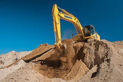
Komatsu America Corp.’s innovation focus for hydraulics centers around improving cycle time and creating a system designed for multifunction, flexibility, and the ability to handle multiple hydraulic attachments. Since 1992, Komatsu has used closed center load sensing (CCLS) hydraulic systems. CCLS systems provide faster, better multi-function capability and activate pumps only as needed. This reduces hydraulic system heat load because pumps are allowed to rest, versus an open center hydraulic system, where pumps are constantly flowing oil.
Recently, Komatsu started using higher displacement variable displacement piston pumps, which operate at lower engine rpm, while maintaining the same high flow rates—basically equal performance with lower fuel consumption for improved efficiency. They have updated the hydraulic tubes on the boom and swing arm with new style tubing that reduces back pressure and improves hydraulic efficiency. Changes were also made to the hydraulic couplings using O-Ring Face Seals, which provide better joint seal and less hydraulic leaking. A dedicated arm quick return circuit that routes oil directly back to tank was added to the larger excavators, for improved arm out-speed to reduce digging cycle time. Improved hydraulic oils such as Komatsu’s semi synthetic HO56 have a broader operating temperature range for improved system performance and extended service life.
Komatsu is also focused on making excavators more intelligent. Integrated machine monitoring systems are now able to sense operator input and make recommendations on changing operating modes for improved fuel efficiency. Multiple work modes now adjust machine performance for various applications such as improved lifting performance, fine grading control, or maximum production. Building on the success of their intelligent dozer product line, Komatsu has leaped forward bringing this technology to their excavators. Dedicated solid state programmable logic controllers integrate hydraulic cylinder position sensors with hydraulic control valves to provide not only machine guidance, but now give the operator semi-automatic machine control.
Using hydraulics is a core competence of Liebherr, a company that is renowned for using hydraulics in its construction machines and even for travel drive where other competitors utilize gear shift transmissions. Using power split solutions allows for further improvements in continuously variable hydrostatic transmissions, a refinement in hydrostatic technology. A new approach to open circuit applications (such as bucket lift and tilt movement) is a valve-less solution where the cylinder movement is barely controlled by a variable pump. Liebherr has also implemented technology that involves hydraulic hybrid concepts that recuperate some energy during reversing or bucket down.
They have also refined and adapted electro-hydraulic power steering for functional safety. Driver comfort is an often-overlooked part of operational safety. Liebherr places special attention in creating a comfortable working environment for operators: the hydrostatic driveline ensures a smooth driving experience; the cabs offer an excellent view of the working area; the dampeners provide best riding comfort; the cooling system is unique—the speed of the fan is dependent on the cooling capacity with thermos-sensors, ensuring optimum fan speed and much lower noise emission due to Liebherr’s hydrostatic driveline concept.
Liebherr has also introduced advances in monitoring and maintenance. Oil refilling periods are extended and controlled by condition monitoring, special oil qualities, and oil sampling in order to operate more sustainably and reduce the total cost of ownership. Gathering and monitoring hydraulic components data (it is relatively easy to monitor pressure, revs, etc.) to evaluate the performance of the hydraulic system has become more important. Liebherr offers the opportunity to analyze these data with LiDAT; Liebherr’s own data transmission and positioning system developed to monitor the optimal equipment operation and enable early recognition of any onset of hydraulics-related issues so that preventive action can be taken to minimize problems.
In line with their sustainability goals, Liebherr has developed fuel saving technologies. The implementation of energy efficiency technologies such as the hydrostatic drive and the Liebherr Power Efficiency system (LPE) optimizes the interaction between drive components. This system is able to adjust the performance power for every working situation enhancing the efficiency of the machine and providing additional fuel savings (up to 25% compared to conventional travel gears).
Link-Belt Excavators Co. is the maker of Link Belt excavators with its X2, X3, X4, and Spin Ace model lines. The X4 are Final Tier 4 compliant with EPA while the X3 are Interim Tier 4 compliant, while emphasizing fuel efficiency and productivity. The Spin Ace with its minimum swing radius is designed to work in tight spaces. The new X4 series has a newly designed and proprietary hydraulics system with electronically controlled main pumps to provide the ultimate in responsiveness, pump torque, cycle times, and pressure loss reduction. This new Ulti-flow hydraulic system combined with an Isuzu engine makes the X4 series of excavators the most productive, mostpowerful, and most fuel-efficient excavators in the market today.
Since 2002, Link-Belt Excavators and HKX Inc. have provided a comprehensive Hydraulic Kit Program providing expanded selection and improved availability. These kits include all the components, instructions, and support needed for complete installation of auxiliary hydraulic systems on Link-Belt excavators not already equipped from the factory with auxiliary hydraulics. These kits are specifically engineered for each Link-Belt excavator model with special attention given to accurate hydraulic flow and pressure, maximizing productivity.
Large or small, it’s hydraulics that supply the muscle
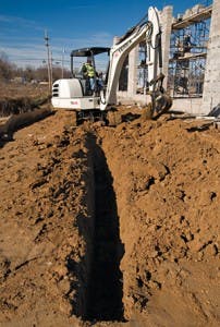
Terex has been a leader in the development of compact excavators and the specialized hydraulics used by this equipment. Compact excavators made their way to North American markets in the mid-1980s and really caught on with contractors in the 1990s when directional drilling specifications called for exposing all existing utilities in the increasingly crowded easements next to roads. Since the 1990s, compact excavators’ popularity in the United States has really taken off. Contractors use them because of their narrow profile, quiet yet powerful operation, versatile attachments, and light footprint. Contractors are finding more and more uses for compact excavators in space-restrictive and urban work environments—such as trenching, grading, site preparation, demolition, landscaping, and utility and pipe installations. The key to this performance is their advanced hydraulics engineering. To meet this demand, their engineers have designed high-performance hydraulic systems for compact excavators that give operators the ability to run multiple machine functions simultaneously, without sacrificing power or performance. A modern hydraulic system will allow the operator the ability to run boom, stick, and swing functions in a smooth, precise, and efficient manner. A modern compact excavator’s hydraulic system gives an operator powerful breakout and lift forces to complete tough jobs with low-effort and smooth joystick control movement.
Terex employs a load-sensing system in its compact excavators that permits the axial piston pump to respond to changes in the load without overloading the engine. This saves fuel and extends the life of the machine’s components. With a load-sensing system, the pump senses the operator’s commands and directs the flow of oil to that function, without stopping the other functions. This develops a smoother operation feeling to the user during any operation. Their compact crawler excavators come in two sizes—mini and midi.
The Terex Mini is designed to function extremely tight spaces without loss of performance. It comes with an adjustable Knickmatik boom system, which enables operators to excavate right next to walls. A further design modification is its top-mounted placement of cylinders on the boom for protection during operations. The larger Terex Midi features the combination of a short tail swing and the Knickmatik boom system along with load sensors that increase work precision and efficiency. It comes with a wide blade for efficient leveling work and circular booms to minimize the working envelope.
Conclusions
Each year brings another improvement and advancement in excavator hydraulic systems. Each refinement builds on the ones that came before. Each new idea is tested out in the field as well as in the marketplace. Not only does it have to show improved efficiency—the gain in efficiency has to be cost effective. The result is an ever-evolving system of greater sophistication and productivity.
