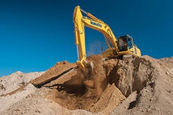
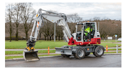
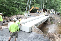
Hydraulics allow excavators to perform their many functions. These machines are not just limited to earthwork. They also lift and place heavy objects such as sewer pipes, equipment, building panels, etc. Their hydraulic systems function within the overall parameters of the machine’s performance (weight, center of gravity, lift point, reach, tractor tread footprint, etc.)
These design dimensions determine the excavator’s tipping point (the point where the load carried by the excavator bucket and the position of the bucket in relation to the excavator’s center of gravity causes the end rollers to lift away from the track rails). Mathematically, the tipping point is the load located at a particular radius. Similarly, the excavator’s rating height is defined by its load, and the vertical distance from the bucket to the ground.
Hydraulics allow excavators to perform their many functions. These machines are not just limited to earthwork. They also lift and place heavy objects such as sewer pipes, equipment, building panels, etc. Their hydraulic systems function within the overall parameters of the machine’s performance (weight, center of gravity, lift point, reach, tractor tread footprint, etc.) These design dimensions determine the excavator’s tipping point (the point where the load carried by the excavator bucket and the position of the bucket in relation to the excavator’s center of gravity causes the end rollers to lift away from the track rails). Mathematically, the tipping point is the load located at a particular radius. Similarly, the excavator’s rating height is defined by its load, and the vertical distance from the bucket to the ground. [text_ad] The excavator’s overall lifting capacity is determined by its tipping point and its hydraulic capacity. Hydraulic lifting capacity can also be altered by equipment configuration. Utilizing the Society of American Engineers (SAE) guidelines for equipment design, loads, and geometry, an excavator’s maximum lifting capabilities can be determined. However, the position of the load can be more complicated than the location of the bucket itself. For example, loads can be suspended from an excavator bucket by means of straps or chains, not just the load of earth within the bucket itself. The geometry and weight of these suspended loads must also be factored into the equipment’s tipping point. In order to ensure against tipping failures, the rated hoist loads are established at weights and distances less than the actual tipping point. Usually, the rated load will not exceed 75% of the tipping load or 87% of the excavator’s hydraulic capacity. These limits establish a factor of safety against tipping of 1.15–1. As a practical matter, these limitations determine the techniques used to optimize operations and to ensure safe and efficient excavation. When excavating at ground level, keep the reach and cable short and close to the excavator’s body. When lifting or digging well below grade, lengthen the cable or reach to ensure that the bucket hinge is located in the optimum lifting location. Long reach excavators are in a category all by themselves. They are used for light digging and lifting, requiring unusually long reach capability. Heavy lifting capacity and long reach cannot be combined in an economic and practical matter. Excavator design is a trade off between these two goals. So long reach excavators are usually used in cohesionless soil at significant depth, such as sand and gravel quarries. Long-reach excavators come with purpose built booms and sticks, linkage cylinders, hydraulic lines, heavy duty and ultra wide undercarriage, and additional counterweights opposite of the bucket location (to improve tipping stability). All of these parameters come together to determine the mechanical specifications of an excavator. Take for example a typical medium sized excavator weighing almost 30 tons. It is equipped with a bucket having a 1.0–1.5 cubic yard capacity capable of lifting up to 1.5 tons. It can move with relative agility and precision across a work site. This moment is made possible by an 8.3-liter displacement diesel engine that can generate up to 350 horsepower. This engine drives a pair of pumps with up to 150 gallons per minute flow rate delivered at a pressure of 4,500 psi. The pumps hydraulic pistons have 5.5-inch diameter faces and 4-inch diameter shafts. Each shafts hydraulic motor can operate at 10–12 revolutions per minute (rpm). These hydraulic pumps are operated from the cab by a pair of joysticks and four pedals, which send electronic signals to eclectic valve blocks integrated with the pumps. These valve blocks in turn connect to the pistons by means of high-pressure hydraulic lines. It isn’t just the bucket and arm that is operated by hydraulics. The excavator moves on tracks which are also hydraulically controlled. The tracks on any piece of earthmoving machinery are driven by hydraulic motors located at one end and a free spinning toothed wheel at the other. The first provides the driving force while the later ensure the track’s alignment and tension on the other rotors.The excavator’s overall lifting capacity is determined by its tipping point and its hydraulic capacity. Hydraulic lifting capacity can also be altered by equipment configuration. Utilizing the Society of American Engineers (SAE) guidelines for equipment design, loads, and geometry, an excavator’s maximum lifting capabilities can be determined.
However, the position of the load can be more complicated than the location of the bucket itself. For example, loads can be suspended from an excavator bucket by means of straps or chains, not just the load of earth within the bucket itself. The geometry and weight of these suspended loads must also be factored into the equipment’s tipping point.
In order to ensure against tipping failures, the rated hoist loads are established at weights and distances less than the actual tipping point. Usually, the rated load will not exceed 75% of the tipping load or 87% of the excavator’s hydraulic capacity. These limits establish a factor of safety against tipping of 1.15–1. As a practical matter, these limitations determine the techniques used to optimize operations and to ensure safe and efficient excavation. When excavating at ground level, keep the reach and cable short and close to the excavator’s body. When lifting or digging well below grade, lengthen the cable or reach to ensure that the bucket hinge is located in the optimum lifting location.
Long reach excavators are in a category all by themselves. They are used for light digging and lifting, requiring unusually long reach capability. Heavy lifting capacity and long reach cannot be combined in an economic and practical matter. Excavator design is a trade off between these two goals. So long reach excavators are usually used in cohesionless soil at significant depth, such as sand and gravel quarries. Long-reach excavators come with purpose built booms and sticks, linkage cylinders, hydraulic lines, heavy duty and ultra wide undercarriage, and additional counterweights opposite of the bucket location (to improve tipping stability).
All of these parameters come together to determine the mechanical specifications of an excavator. Take for example a typical medium sized excavator weighing almost 30 tons. It is equipped with a bucket having a 1.0–1.5 cubic yard capacity capable of lifting up to 1.5 tons. It can move with relative agility and precision across a work site. This moment is made possible by an 8.3-liter displacement diesel engine that can generate up to 350 horsepower. This engine drives a pair of pumps with up to 150 gallons per minute flow rate delivered at a pressure of 4,500 psi. The pumps hydraulic pistons have 5.5-inch diameter faces and 4-inch diameter shafts. Each shafts hydraulic motor can operate at 10–12 revolutions per minute (rpm). These hydraulic pumps are operated from the cab by a pair of joysticks and four pedals, which send electronic signals to eclectic valve blocks integrated with the pumps. These valve blocks in turn connect to the pistons by means of high-pressure hydraulic lines.
It isn’t just the bucket and arm that is operated by hydraulics. The excavator moves on tracks which are also hydraulically controlled. The tracks on any piece of earthmoving machinery are driven by hydraulic motors located at one end and a free spinning toothed wheel at the other. The first provides the driving force while the later ensure the track’s alignment and tension on the other rotors.