The Greek philosopher Archimedes once said, “Give me a place to stand, and I can move the world.” He was talking about leverage, but the same force multiplying principle applies to hydraulics. Simply put, hydraulics is a way to multiply force by utilizing an incompressible fluid (typically oil). The initial force is applied at one end of the hydraulic system, transmitted through the fluid, with constant pressure to the other end.
For example, a force of 10 pounds applied to one end of a system by a piston (fitted into what is referred to as the “master cylinder”) with a 1-square-foot cross sectional area resulting in an applied pressure of 10 pounds per square foot. At the other end of the hydraulic system, the cross sectional area of the receiving piston (set within the “slave” cylinder) is 10 square feet. The transmitted pressure of 10 pounds per square foot therefore becomes a force of 100 pounds.
The Greek philosopher Archimedes once said, “Give me a place to stand, and I can move the world.” He was talking about leverage, but the same force multiplying principle applies to hydraulics. Simply put, hydraulics is a way to multiply force by utilizing an incompressible fluid (typically oil). The initial force is applied at one end of the hydraulic system, transmitted through the fluid, with constant pressure to the other end. For example, a force of 10 pounds applied to one end of a system by a piston (fitted into what is referred to as the “master cylinder”) with a 1-square-foot cross sectional area resulting in an applied pressure of 10 pounds per square foot. At the other end of the hydraulic system, the cross sectional area of the receiving piston (set within the “slave” cylinder) is 10 square feet. The transmitted pressure of 10 pounds per square foot therefore becomes a force of 100 pounds. [text_ad] The piping connecting the two pistons can be of any shape, configuration, or length due to the incompressible nature of the hydraulic oil. Furthermore, one master cylinder can apply force to any number of slave cylinders. This simple system is also very efficient. Again, due to the incompressible nature of the oil, almost all of the applied force from the master cylinder acts on the slave cylinder. The tradeoff between the master and slave cylinder is between the distance of movement and the applied force. This is known as “hydraulic multiplication.” In our example, the resultant force on the slave cylinder is 10 times greater than the applied force created by the master cylinder due to the slave cylinder’s greater surface area. But the slave cylinder’s piston will move only 1 foot for every 10 feet that the master cylinder’s piston moves. Lever arms and block and tackles operate on the same mechanical principles. So one garage repairman working a hydraulic lever can generate enough force to lift a large car on a rack well above his head. Brakes on a passenger car operate the same way to multiply the force of the driver’s foot pressure to apply enough force to the brake systems master cylinder to transmit enough force to the slave cylinders at each wheel’s brake pad to slow or stop a heavy car moving at high speed. Mechanical hydraulic systems utilized by vehicles and equipment are connected by a series of valves and piping to a pump that supplies high pressure oil. It is vitally important that these connections retain their tight seals. Seal integrity is not just important for preventing the loss of hydraulic fluid; it is also important to prevent the entrainment of air bubbles in the fluid itself. Unlike hydraulic oil, air is compressible. So if a bubble is trapped within the system transmission lines, the force generated on the system will go towards compressing the air bubble instead of being directly applied to the slave cylinder. This greatly reduces the effective force and overall efficiency of the system, often to unsafe levels. This is why brakes can fall “mushy” and why a car mechanic will “bleed” the air out of a hydraulic brake line to restore its proper performance. Hydraulics and Heavy Equipment Operations Hydraulic equipment applies the scientific principles described above in order to perform useful work via multiple machine functions: Engines and motors operate a pump, these pumps pressurize the hydraulic fluid (mineral oil polyalphaolefin or organophosphate ester), the fluid travels through hydraulic tubes to actuators, and the actuators drive the arm or bucket doing the excavation. The fluid is recycled through the system, passing through filters on the way back to the pump. The above description is somewhat over simplified. An actual hydraulic system requires a wide range and variety of valves, pumps, filters check valves, counterbalance valves, hydraulic cylinders, pump filters, tubes, and seals capable of withstanding high pressures. In fact, all the materials (metals, steel and stainless steel alloys, bras, woven wire, and synthetics) used to make a hydraulic system must be extremely strong and durable. At the top of this list is titanium, often used in extreme high-pressure systems operating at more than 50,000 psi. Crawler excavators are mobile work machines with at least six hydraulic actuators: boom, lift arm, bucket (all three for equipment), swing, travel left, and travel right. This diversity of working functions places special demands on its hydraulic system. During operations, a crawler excavator’s hydraulic system may be required to conduct all movements smoothly, simultaneously, sensitively, and independently. High-volume flows of hydraulic fluids will be required to ensure fast movements during excavation. This is achieved with differential cylinders, whose hydraulic flow raters are twice the installed pump volume. An excavator’s drive system should convert 100% of the engine output hydraulically. And its hydrostatic power will be much higher than the maximum engine output. Each movement’s volume flow is optimized; due to economic reasons, the number of pump circuits is limited, so this movement optimization is achieved by combining or separating pump circuits. For that purpose, independent movement is achieved by tuning the hydraulic flows by means of control valves, although more advanced systems utilize and software and sensor technology. It is the newer hydraulic control systems that are using intelligent electric systems and electronics. Other earthmoving equipment utilize different hydraulic system configurations. A skid loader and front end loaders (which are more of bulk material handlers than a true excavator) also depends on hydraulics. Its large front end bucket requires three pairs of hydraulic pistons for operation: one pair that raises and lowers the bucket, another pair that vertically tilts and rotates the bucket to allow loading and dumping, and a last pair that can split the bucket to allow it to grab objects like steel I-beams or logs. Dump trucks also use hydraulics, though in a much simpler configuration. Depending on the make and model, dump trucks have either one or two large hydraulic cylinders to raise and lower the truck bed. These hydraulic cylinders have two unique design futures. First, they telescope in multiple segments to allow for a long movement length, and they tend to be more powerful in order to lift the heavy load of a fully loaded dump.The piping connecting the two pistons can be of any shape, configuration, or length due to the incompressible nature of the hydraulic oil. Furthermore, one master cylinder can apply force to any number of slave cylinders. This simple system is also very efficient. Again, due to the incompressible nature of the oil, almost all of the applied force from the master cylinder acts on the slave cylinder.
The tradeoff between the master and slave cylinder is between the distance of movement and the applied force. This is known as “hydraulic multiplication.” In our example, the resultant force on the slave cylinder is 10 times greater than the applied force created by the master cylinder due to the slave cylinder’s greater surface area. But the slave cylinder’s piston will move only 1 foot for every 10 feet that the master cylinder’s piston moves.
Lever arms and block and tackles operate on the same mechanical principles. So one garage repairman working a hydraulic lever can generate enough force to lift a large car on a rack well above his head. Brakes on a passenger car operate the same way to multiply the force of the driver’s foot pressure to apply enough force to the brake systems master cylinder to transmit enough force to the slave cylinders at each wheel’s brake pad to slow or stop a heavy car moving at high speed.
Mechanical hydraulic systems utilized by vehicles and equipment are connected by a series of valves and piping to a pump that supplies high pressure oil. It is vitally important that these connections retain their tight seals. Seal integrity is not just important for preventing the loss of hydraulic fluid; it is also important to prevent the entrainment of air bubbles in the fluid itself. Unlike hydraulic oil, air is compressible. So if a bubble is trapped within the system transmission lines, the force generated on the system will go towards compressing the air bubble instead of being directly applied to the slave cylinder. This greatly reduces the effective force and overall efficiency of the system, often to unsafe levels. This is why brakes can fall “mushy” and why a car mechanic will “bleed” the air out of a hydraulic brake line to restore its proper performance.
Hydraulics and Heavy Equipment Operations
Hydraulic equipment applies the scientific principles described above in order to perform useful work via multiple machine functions: Engines and motors operate a pump, these pumps pressurize the hydraulic fluid (mineral oil polyalphaolefin or organophosphate ester), the fluid travels through hydraulic tubes to actuators, and the actuators drive the arm or bucket doing the excavation. The fluid is recycled through the system, passing through filters on the way back to the pump.
The above description is somewhat over simplified. An actual hydraulic system requires a wide range and variety of valves, pumps, filters check valves, counterbalance valves, hydraulic cylinders, pump filters, tubes, and seals capable of withstanding high pressures. In fact, all the materials (metals, steel and stainless steel alloys, bras, woven wire, and synthetics) used to make a hydraulic system must be extremely strong and durable. At the top of this list is titanium, often used in extreme high-pressure systems operating at more than 50,000 psi.
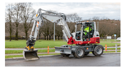
Crawler excavators are mobile work machines with at least six hydraulic actuators: boom, lift arm, bucket (all three for equipment), swing, travel left, and travel right. This diversity of working functions places special demands on its hydraulic system. During operations, a crawler excavator’s hydraulic system may be required to conduct all movements smoothly, simultaneously, sensitively, and independently. High-volume flows of hydraulic fluids will be required to ensure fast movements during excavation. This is achieved with differential cylinders, whose hydraulic flow raters are twice the installed pump volume.
An excavator’s drive system should convert 100% of the engine output hydraulically. And its hydrostatic power will be much higher than the maximum engine output. Each movement’s volume flow is optimized; due to economic reasons, the number of pump circuits is limited, so this movement optimization is achieved by combining or separating pump circuits. For that purpose, independent movement is achieved by tuning the hydraulic flows by means of control valves, although more advanced systems utilize and software and sensor technology. It is the newer hydraulic control systems that are using intelligent electric systems and electronics.
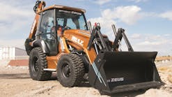
Other earthmoving equipment utilize different hydraulic system configurations. A skid loader and front end loaders (which are more of bulk material handlers than a true excavator) also depends on hydraulics. Its large front end bucket requires three pairs of hydraulic pistons for operation: one pair that raises and lowers the bucket, another pair that vertically tilts and rotates the bucket to allow loading and dumping, and a last pair that can split the bucket to allow it to grab objects like steel I-beams or logs.
Dump trucks also use hydraulics, though in a much simpler configuration. Depending on the make and model, dump trucks have either one or two large hydraulic cylinders to raise and lower the truck bed. These hydraulic cylinders have two unique design futures. First, they telescope in multiple segments to allow for a long movement length, and they tend to be more powerful in order to lift the heavy load of a fully loaded dump.