Introduction
Concrete has been around since ancient times. Concrete and mortar have been used to hold together bricks and create smooth surfaces by every civilization. Today concrete is the foundation (literally) of modern construction techniques of all types. Our roadway system primarily utilizes concrete pavement for road construction, according to the Portland Cement Association:
Concrete played a major role in the construction of the US Interstate Highway System during the past 60 years . . . The national highway system, which includes the nearly 45,000-mile interstate system, carries 40% of the nation’s total traffic, including 70% of the commercial traffic and 90% of the tourist traffic, according to the Federal Highway Administration [FHWA]. About 60% of the interstate system is concrete, especially in urban areas where FHWA anticipates heavy traffic loads. Concrete was selected, in part, because of its durability.
These roadways are constructed with specially designed heavy equipment, differing in both kind and technique from the equipment used to install asphalt pavement. And while this equipment provides an impressive level of productivity, it has limitations based on theconcrete materials being used.
Concrete Characteristics
What exactly is concrete? First used extensively by the ancient Romans, concrete is a construction material made from two active components (Portland cement and water) and two inert components (fine and coarse aggregate). The active ingredients chemically bond upon mixture while the inert ingredients provide mass and volume. Fine aggregate is usually sand while coarse aggregate can be gravel, crushed stone, or recycled concrete chunks. A typical mixture ratio is one part cement to three parts sand to three parts aggregate. When making concrete, the dry ingredients are mixed prior to the addition of water. The chemical reaction binding the concrete together occurs when water interacts with the Portland cement.
Portland cement is the key ingredient of concrete—it’s what holds the concrete together. It is not a result of the concrete drying out and the water evaporating. Loss of water results in reduction of the hydration process. Instead, the chemical reaction called hydration causes the concrete to harden. Concrete cement must be kept as moist as possible to ensure a complete hydration process.
Concrete is strong in compression but weak in tension. This strength is inversely proportional to the amount of water mixed with the dry ingredients. More water makes concrete more fluid and easier to work with while reducing strength. Less water increases the concrete’s strength but makes its stiffer and harder to work with.
Depending on the actual mixture, concrete compressive strengths can vary from 2,500 pounds per square inch gauge (psi) for residential concrete to 4,000 psi and higher in commercial structures. For special applications, concrete strengths exceeding 10,000 psi are utilized. By comparison, concrete tensile strength is only about a tenth of its compressive strength (300–700 psi). Its flexural or bending strength is similarly weak at 400–700 psi. Concrete’s modulus of elasticity varies from 14,000–41,000 MPa.
Concrete can be formed and poured into a wide variety of applications and shapes whose anticipated loads will result in considerable tensile and flexural forces. These loads would result in cracking and failure of the concrete by itself, so concrete is reinforced with structural steel. The steel is included to carry the anticipated tensile loads. Structural ASTM A36 steel, for example, has a tensile strength against yield of 36,250 psi.
At minimum, the steel can consist of “shrinkage and temperature” mesh that protects the concrete from tensile strain caused by internal stresses generated by variable temperatures due to long-term exposure to climate conditions. Individual rods of steel (referred to as “rebar”) can be installed within and along the length of the proposed concrete structure at sizes, thickness, and directions required by the structure’s engineering analyses. This rebar can be unidirectional, laid across angles, bundled into thicker rod, and extended and anchored into adjacent structures and foundations for stability.
So what does a typical cross-section of concrete pavement look like? At the bottom, the pavement consists of a compacted subgrade with a required optimum density for the soil underling the pavement. Then comes a sub-base typically consisting of a minimum of 4 inches of gravel (though some designs do not include this layer). Above this is the surface run of reinforced concrete pavement, usually a minimum of 4 inches thick with steel rebar or mesh whose size, diameter, length, and strength will be specified by the engineer in accordance with anticipated traffic conditions.
Comparisons With Bituminous Asphalt
Concrete pavement is referred to as “rigid” pavement given its high compressive strength and steel reinforcement. It does not bend under applied vehicle loads. But it is not the only type of pavement. Also used extensively is bituminous asphalt, referred to as “flexible” pavement. This is an over-simplification—concrete can bend somewhat and asphalt can be relatively stiff—but these terms provide a good general explanation of how pavement interacts with applied loads, environments, and underlying subgrades.
The configuration of asphalt pavement differs somewhat from concrete pavement. From top to bottom, bituminous asphalt pavement consists of a relatively thin wearing surface course, a bituminous asphalt base of at least 3–4 inches, a sub-base of gravel or stone measuring 4 or more inches in thickness, and a compacted soil subgrade.
Their primary difference lies in how they distribute applied vehicle loads to the underlying subgrade. Being rigid, concrete pavement distributed loads over a wide area of the subgrade. For the most part, it is the concrete slab itself that provides the bulk of the pavement’s structural strength and load capacity. Bituminous asphalt pavement tends to be less stiff and weaker than concrete on a unit basis (deforming more under the same applied loads). Therefore, it doesn’t spread out loads over as wide an area of subgrade as does concrete pavement. It requires thicker layers and depends more on the strength of the compacted, underlying soil subgrade.
Concrete can also be enhanced and augmented by reinforcement, texture, and color in ways not possible for asphalt. This greatly increases the durability and performance of concrete pavement, allowing it to often outlast bituminous asphalt in the same environment by 10–15 years before needing retaliation. However, this often comes with higher up-front initial construction costs since reinforced concrete can be significantly more expensive to install (however, a sharp increase in the price of oil—a major component in the manufacturing of asphalt—can negate this price difference). It was a desire to reduce these upfront costs that led to the development of the concrete paving machines and equipment that are the subject of this article.
These materials have differing strengths, weaknesses, and applications. As mentioned above, concrete pavements are stronger and more durable, but initial construction costs are higher. Furthermore, asphalt pavement can be laid in less time, yet the required frequency of repair for concrete pavement is much lower and it is less susceptible to damage from extreme weather. Concrete surfaces are also not damaged by oil leaks and fuel spills like asphalt surfaces are.
But when repair and maintenance are required, these activities are easier to perform on asphalt pavement. Maintenance on asphalt pavement can be confined to small areas (such as fixing pot holes) instead of having to replace an entire concrete slab section. Performance wise, asphalt has better skid resistance and traction while snow and ice melt faster on asphalt than concrete due to its color.
Concrete Pavement Types and the Use of Joints
Various types of concrete pavement designs are available to highway engineers. These designs utilize different types of joints and steel reinforcement layouts to control the forces that could damage the pavement—including vehicle and equipment loads, shrinkage of the concrete itself during curing, and environmental changes (precipitation and temperature fluctuations). Over time, these forces can cause cracks to appear in the main slabs of the pavement.
Joints can be considered to be controlled cracks. They provide a gap in the pavement to allow a degree of expansion and movement. By allowing a “breathing space” for the concrete, joints largely prevent the accumulation of stresses within the slab itself, and thus prevent the formation of cracks. The locations, intervals, and extent of joints are determined by the designer based on anticipated loads and forces.
The use of joints allows for a jointed concrete pavement (JCP) design as distinguished from the continuously reinforced concrete pavement (CRCP). These two types represent the main categories of pavement designs. JCP has traverse joints set at regular intervals (typically about 15 feet). It also utilizes longitudinal joints along the pavements’ direction and centerline. These joints are connected with steel tie bars. Design standards govern the actual details of the joints themselves.
CRCP, on the other hand, utilizes both longitudinal and traverse steel rebars. It only utilizes joints at construction joints between changes in roadway layout such as a transition from a straight section to curve. The function of this rebar is to keep traverse cracks tightly closed. This prevents cracks from widening and minimizes subsequent stresses in the concrete slab due to traffic loads.
A Power Curbers & Power Pavers SF3000 working in Turkey
But which type of rigid pavement design is best? CRCP has superior long-term performance, durability, and very low maintenance, and is the preferred method for new and reconstructed pavement. JCP is often utilized for aesthetic reasons (to minimize cracking that would be obvious to pedestrian traffic), parking areas, and other low-impact pavements (roadways with crosswalks, sidewalks, etc.), railroad crossings, approach structures and ramps, intersections, and transitions to adjacent asphalt pavement.
The overall goal is to design a rigid pavement with a performance period of at about 30 years, with a 15-year performance period for road sections that involve the widening and upgrade of existing pavement. The actual design methods and analytical tools can befound in the AASHTO Guide for Design of Pavement Structures (1993).
Concrete Pavement Construction Techniques
Once the design is completed and approved, actual construction can begin. As with most things, concrete pavement construction starts at the bottom with its subgrade and base layers. A well compacted subgrade is essential to provide adequate density, moisture content, durability, stability, resistance strength, and modulus. Poor and poorly prepared soil will cause differential settlement and cracking of pavement. Expansive or intrinsically weak in situ soil may not meet a construction project’s strength specifications. Strengthening and reinforcing subgrade soil may be necessary for either new construction or rehabilitation. These inadequate soils can be treated with additives such as lime, dry cement, fly ash from coal combustion power plants, asphalt mixture, or additional select fill.
Good materials in themselves do not guarantee acceptable durability and long-term performance. Proper construction techniques and practices are also necessary. Poor construction practices can result in premature failure of the pavement. The overall construction process is somewhat complicated, involving multiple steps to ensure the proper performance of the whole pavement. After proper preparation of the subgrade, these steps include placing and compacting aggregate for the sub-base, placing and anchoring steel rebar, setting forms, production, and transport of the concrete to the work site, placing and spreading the concrete, installing joints, preparing the pavement’s surface, and allotting sufficient time for curing.
Steel rebar can be placed either longitudinally or horizontally. Requirements can vary from state to state with Grade 60 deformed steel bars typically used. ASTM A966 Type R is sometimes used if the recycling of steel is encouraged. Higher grades, such as Grade 70/75, can be used, but may offer only marginal improvements in performance. Horizontal traverse placed steel is used to reinforce the main longitudinal steel. The actual depth, diameter, and placement intervals of the steel are determined by the design engineer and placed according to the engineer’s plans. In general, the amount of steel increases with the proposed thickness of the pavement, with two layers of steel being commonly used for pavement thicker than 12 inches.
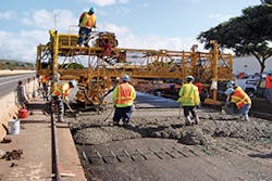
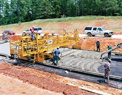
Slip-form placement utilizes the forms of the slip-form paving machine to form the concrete and mold it in place so that it is finished at the proper grade and alignment. These machines ride on steel wheels and their weight has to be supported by forms uniformly supported with a strong sub-base. Smaller machines (used for irregular or narrow placement areas, ramps, and turnarounds) utilize three long steel roller tubes that propel the screed and concrete to the level of the top of the forms. Heavier machines (such as those used for bridge decking) can ride on steel pipes placed adjacent to the forms. It utilizes a longitudinal screed roller suspended from a truss system that spans the pavement forms. Concrete is fed by an auger mounted at the front and the roller screeds smooth the concrete surface as the machine moves forward.
Cement paving an airport in Italy with a Power Paver
With fixed-form paving, on the other hand, forms are set along the boundaries of the pavement to define the extant of this placement prior to the pouring of the pavement. These forms hold the concrete in place and define the edges of concrete placement along the edges of the pavement. Physically, the forms are usually made from 0.2-inch thick metal pieces 10 feet long with a height equal to that of the pavement thickness, and wide bottom bases for stability. They should be free of bends or kinks. The concrete used tends to be less stiff with a higher slump than the concrete used in slip-form paving. The forms should be thoroughly cleaned to prevent irregularities and oiled to allow for ease of removal once the concrete is cured. This technique tends not to be as productive as slip forming due to the time and labor required to initially set and then later remove the forms. Therefore, it is usually required for special situations such as ramps and small areas, leaving most of the main concrete paving to slip-form machines.
The setting of the fixed forms largely determines the quality and smoothness of the concrete surface. The best placed forms are installed securely and as close as possible to the final pavement elevations, alignment, and grades. Unstable forms are to be avoided as they can result in a pavement with irregular or rolling surfaces. Both the top and interior surface of the forms should be placed as straight as possible relative the vertical of the pavement alignment, with variances correct by use of the straight edge or string line. Prior to actual pouring of the concrete the forms are checked for overall straight alignment and horizontal curvature.
Concrete Paving and Roadway Construction Equipment Suppliers
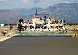
Terex Bid-Well 5000 and 6500 airport pavers are capable of paving streets, highways, airports, and other slab-on-grade projects. Their design allows them to pave a wide variety of surfaces. They can match flat, parabolic, crowned, super-elevated, and tapered surfaces. They feature patented Rota-Vibe, which helps achieve a more uniform concrete surface with the desired density. It aids the sealing of difficult-to-finish concrete due to harsh mix designs, unpredictable delays, low slump specifications, and wind exposure, causing abnormal surface drying. During paving operations, the paving carriage strikes off, paves and textures the concrete with augers, and paving rollers, while utilizing a drag pan and texturing.
The smaller Terex Bid-Well 5000 paver is unique in the wide range of jobs that it can be used. It can perform in heavy highway and road paving environment, airport aprons, runways, and taxiways. With its 48-inch truss depth and standard paving widths ranging from12–68 feet, it is able to place paving concrete to depths of up to 30 inches. Its design allows for ease of transport, adjustment and the ability to pave oddly shaped slabs. For unique applications using two mats of steel, the paver can be equipped with vertical vibration to enhance concrete consolidation. A pressure washer is available for convenient cleanup.
The larger Terex Bid-Well 6500 model features Terex Hydra-Mation string line sensing control for elevation and steering. The paver is designed and built for heavy-duty, thick airport paving. Its design allows for its flexible use in paving approaches, runways, aprons, and taxiways, and it offers paving widths from 12–68 feet. It comes standard with internal concrete vibration systems, hydraulically powered up and down legs, and grade sensing hydramation. Like the 5000 it can be coupled with the Terex Bid-Well Vertical Vibration System, and the pressure wash system is standard for convenient cleanup.
Liebherr is a supplier of truck-mounted concrete pumps that can be used to provide materials for paving, decking, and flooring operations. With patented XXT support equipment their pumps can be utilized in a wide variety of applications. Its concrete pumping rate can vary in output from 62–167 cubic meters per hour. Their trailer concrete pumps can be used in a variety of ways from stationary positions on construction sites, irrespective of the distance or height to be pumped. Depending on the type of application, it can be operated either with a high output or with high concrete pressures, subject to the type and actuation (piston side or rod side). The crawler concrete pump is designed to be flexible on the construction site; it can even be maneuvered by remote control.
Power Curbers & Power Pavers produces concrete slip-form pavers and curbers. The Power Pavers SF-1700 is an economical and compact slip-form paver. It is designed for paving widths from 10–24 feet, and can also handle half-width paving, congested city street paving, and rural roads. Its operational weight ranges from 39,000–45,000 pounds. Its size allows it to produce a smooth surface when paving smaller roads or when concrete supply is limited. Since it only requires 29 inches of side clearance, the SF-1700 can be used for rehab projects or other congested sites where larger machines cannot operate easily. All machines now offer a Controller Area Network bus control system.
Their best selling machine, the Power Paver SF-2700, is a two-track slip-form paver designed to pave between 12 feet and 27 feet wide. These dimensions make the SF-2700 ideal for residential streets, street rehabilitation, and overlay work. It has a low profile and narrow side clearance of 29 inches which simplifies rehab work on cramped city streets. Its simple design maximizes productivity. The operator has an excellent view of all functions around the machine and its low center of gravity makes it easy to transport. It can come equipped with electronic sensors and easy-to-mount vibrators. As a slip-form paver, it does not have to work with forms. In addition to standard road jobs, the SF-2700 can pave up to 32 feet wide with extensions. With a paving depth of up to 16 inches, it can even be used in airport work. Standard features include a reversible auger system, split tamper bar, and hydraulic strike-off for metering concrete. Optional equipment includes keyway inserters, bar inserters, integral curb molds, and a variety of finishing options including belt or float.
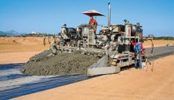
The Power Paver SF-3000 is Power’s heavy-duty, high production slip-form paver for use on streets, highways, and airports. At 65,000 pounds, or up to 90,000 pounds at full-width paving, the SF-3000 has the weight and stability to handle large jobs at high production rates up to 20 inches thick. The larger SF-3000 comes equipped with hydraulic loading legs, which extend to allow for easy loading and transport. It has the ability to change widths quickly, making the SF-3000 very productive. Like the SF-2700, the SF-3000 is simple to set up and operate, and has a choice of either electronic sensors. The SF-3000 also features side forms, which hydraulically widen 3 inches and raise 3 inches allowing the operator to back over the previous day’s pour and to start paving right off the header, eliminating gaps and blow-out and resulting in less hand work. The 18-inch diameter auger is powered to spread large amounts of concrete entering the paving chamber. Standard features on the SF-3000 allow for paving from 12–27 feet wide, with optional extensions to 32 feet wide. Other options on the SF-3000 include keyway inserters, bar inserters, dual-speed track motors, and a variety of finishing options including belt or float.