Operation and Maintenance of Heavy Equipment Oils, Lube, Coolant, and Hydraulics Systems
Oil, lube, and coolant are standard offerings at any garage or quick oil change shop and are familiar to all car owners. Heavy equipment operators utilize the same systems and have the same maintenance requirement, though on a much larger scale. And, in addition to oil and lube, heavy earth moving equipment also requires hydraulic fluids managed by a hydraulic system to function. Through mature technologies and universal applications, none of these systems are standing still with new innovations, deigns, and improvements entering the heavy equipment market all the time.
Engine Oil
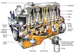
An engine’s oil system is a circular flow designed to ensure that clean oil is delivered where it is needed on the engine’s moving parts at a designated temperature, pressure, and flow rate. Its starts with oil stored in the engine’s oil sump located in a pan below the engine body. The oil pan often encloses the entire lower portion of the engine block in order to ensure complete capture of the used oil.
The oil is drawn from the sump through tubing by means of an oil pump. As the oil is discharged from the pump it is forced through an oil filter. The heart of the system, the oil pump, is quite intricate in design and rugged in operation. Usually a gear type pump, the driving force is provided by a pair of meshing gears. Oil fills the spaces between the aligned teeth of the opposing gears as they turn. The spinning of the gears continues to expel the oil to the discharge hose that caries the oil under pressure into the oil filter.
The filter traps impurities that could actually harm the engine allowing only clean smooth oil to be used, retaining dirt particles from the passing oil. Oil filters are removed and replaced as part of an engine’s regular maintenance cycle depending the number of hours of operation. It is especially critical that oil is cleaned prior to coming into contact with the engine bearings.
Discharge tubes from the pump and the filter carry oil to the engine’s main bearings and drilled holes through the engine block. This is referred to as the oil gallery. At some point along these tubes, an oil pressure gauge is installed to monitor the oils operating pressure. A minimum pressure is required to force the pump through the filter and around engine fittings and linkages. From the main bearings, the oil is forced through drilled feedholes into the crankshaft, connecting the pistons as well as the bearings of the connecting rod. In order to increase the amount oil in contact with their surfaces, some rods are designed with grooves and holes that can retain more oil.
In doing so, the oil lubricates the bearings of the piston pin and the walls of the piston cylinder get a coating of oil to lubricated the motion of the enclosed piston. Each individual piston is fed oil via a branch line from the main engine pipeline. Other branch pipelines deliver oil to gears, timing chain, and drive of
the camshaft. Excess oil then drains back into the sump.
By this time, the oil is very hot, having passed through an operating engine. The oil sump is not just of storing oil for use in later feed cycles, it also acts as a cooler. This is designed to prevent overheating of the oil. Cooling is achieved by the flow of engine coolant adjacent to the tubes carrying the hot oil. From there,
the coolant transports the excess heat to the engine’s radiator.
Additional heat can be expelled directly through the walls of the sump. While in the sump, the excess heat of the incoming oil is transferred to the walls of the sump. During its time in storage, its excess heat is radiated to the surrounding air, cooling the oil back down to a useable temperature. Time of storage in the sump depends on usage requirements, pump rates, the number feed cycles per minute, and the capacity of the oil sump. Figure 1 shows a simplified engine oil system.
Why does an engine need an oil circulating system? It is not just to allow surfaces to slide past each other more efficiently by minimizing the contact surface friction coefficient. It minimizes wear and tear to both contact surfaces by sealing the clearances between the various moving parts (piston cam and cylinder wall, ball bearing and rotating shaft, etc.). Maintaining a proper thickness of oil over all contact surfaces prevents physical contact. Oil also absorbs heat from the engine and its moving parts. The oil transfers this heat to the oil pan during its use cycles, thus helping to prevent the engine from overheating. Oil also acts as a cushion against the sudden application of heavier loads or increased torque. Oil seals off open spaces at it fills and covers, preventing gas blow out from the pistons.
Once filtered and cleaned, the oil can then prevent the impingement of dirt and dust particles which could foul moving parts over time. Rock, dust, dirt, sand, and water working their way into engine components will form an abrasive that will significantly reduce bearing life. Recycling the oil through the filter removes these impurities with each use cycle. In effect, oil cleans the engine.
What could go wrong with lack of proper maintenance? Crankshafts can get worn, reducing the engine pressure and causing the oil to be thrown all over the engine’s inside. The oil splash won’t be contained by the piston rings and the engine will actually burn the excess oil. This creates a negative feedback loops where the quantity of oil is reduced by the burning which in turn leads to greater wear and tear on the engine which then leads to more wasting of oil, and so on. Keeping a good seal in turn prevents leakage of the fuel air mixture normally combusted in the piston cylinder. This, in turn, comes back to properly maintaining the piston’s oil controlling ring so that it keeps the minimally required thickness of oily film on the inside to the cylinder walls. Even with the best maintenance, oil degrades over time, and so oil will always need to be changed at regular intervals.
Lube Jobs
Note that oil change and lube job are two different things. Though oil lubricates the engine, a true lube job involves oiling the suspension system, drivelines, and the vehicle chassis. None of these vehicle parts shares oil with the engine oil system. The goal is to insure free movement of the equipment undercarriage while minimizing wear and tear. In the past, wheel bearings would also be part of a lube job, but most wheel bearing housings are sealed and rarely go bad unless there has been physical damage to the housing resulting in a leak of its lubricant.
One method to ensure proper oil and lubrication is the automatic lubrication system. Manual lubrication takes at least 30 minutes, to an hour each workday. This can be delayed by bad weather, and in any case reduces overall productivity by taking equipment out of service. Performing oil changes manually in the field presents certain safety issues and depends on the logistical availability of the lube truck. Heavy equipment lubrication can be more complicated with every pin on a bucket or arm needing lubrication in multiple positions. Manual oil change and lubrication requires trained personnel in an industry that is already facing a shortage of skilled workers. Significant labor savings can be achieved by the use of automat lubrication systems for daily and weekly lubrication points using manual lubrication only for small equipment, points that cannot be reached by machine, and bearing that require lubrication only at extended intervals.
By maximizing automatic lubrication systems, almost an hour of additional productivity can be achieved each workday. Machines can deliver the exact amount of grease needed and in controlled even applications, minimizing waste. Machine lubrication does not pose the same safety problems, nor is it affected by
weather conditions. A typical automatic lubrication system includes an electric pump with flow meters and control valves, supply hoses and feedlines, lubricant storage reservoir, and malfunction reporting systems. Divider valves control grease flow, directing it to where it is needed and in the proper quantities required by each pin or bearing location. Proximity switches indicate a successful lube application and signal the pump to shut off.
Hydraulics Systems
Hydraulic systems are force multipliers. They transmit force along hoses and lines to where it is needed to operate the business end of the heavy equipment whether it be dozer blade or excavator bucket. By utilizing an incompressible fluid (such as oil), pressure applied at one end is transmitted without loss. Due to the laws of hydraulics, the pressure stays constant throughout the fluid, which can result in increased force at the receiving end. For example, 100 pounds of force applied on a fluid in a pipeline 1 square inch in cross section area is subject to a pressure of 100 psi. Should the receiving end of this fluid have a cross-sectional or contact area of 10 square inches, the resultant applied force is actually 1,000 pounds (100 psi x 10 square inches). However, the distance that the surface is raised or move the equipment is moved at the receiving end is reduce to 1/10. So, if the applied load in this example moves 10 feet, the receiving load moves only 1 foot.
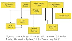
This is a result of hydraulic multiplication. In most hydraulic systems there is a master cylinder at the force application end and a slave cylinder at the receiving end connected by an hydraulic pipeline or hose. So, a smaller master cylinder can transmit the same pressure to a larger slave cylinder, or multiple cylinders. With the slave cylinder having larger diameters, the pressure results in increased force generated by the slave cylinder. The movement of the slave cylinder, on the other hand, is inversely proportional to the difference in the cylinder cross section area. The same operating principles apply to all simple machines (lever arms, block and tackle, etc.). And it not just the business end of the machine, the simple act of braking relies of efficient hydraulic systems. Figure 2 shows the layout of a typical heavy equipment hydraulics system.
Such a system requires an extensive and complicated series of pipelines, hoses, valves and connections—none of which can be allowed to leak. The list of required hydraulic system parts is long and varied: valves, pumps, filters check valves, counterbalance valves, hydraulic cylinders, pump filters, tubes, and seals capable of withstanding high pressures. The hydraulic oil used as a working fluid to transmit force throughout the system is under extremely high pressure and the smallest leak can result in significant loss of fluid.
Nearly as bad, leaks can allow air to enter the system leading to entrained air bubbles that short circuit the transmission of force down the lines. When subject to pressure, the air bubbles become compressed, resulting is loss of applied force at the slave cylinder. As a consequence, hydraulic lines can feel “mushy”—a particularly dangerous condition for vehicle brake systems. To prevent leaks, the fittings and appurtenances must be durable and strong, capable of resisting pressures as high as 50,000 psi. To achieve the necessary level of resistance and strength, hydraulic systems utilize materials such as titanium, steel and stainless steel alloys, bras, woven wire, and synthetics.
The force is generated by the pumps that circulate the fluid through the hydraulic system. There are several types of oils utilized as hydraulic working fluid: mineral oil polyalphaolefin or organophosphate ester. Being incompressible, the fluid carries the force directly to the actuators that physically move the arms, buckets, blades, and load beds of heavy earth moving equipment. As with engine lubricant oil, the hydraulic fluid is recycled through the system passing through a filter that removes impurities. The need for removing impurities is less about overheating and wear and tear so much as it is about maintaining the required levels of force.
The number of actuators varies for each type of machine. The more complicated the movement, the more actuators required. For example, crawler excavators require a minimum of six actuators: boom, lift arm, bucket, swing, travel left, and travel right. The excavator’s tracks also hydraulically controlled. The tracks are not only driven by hydraulic motors located at one end (to provide driving force) but by a free spinning toothed wheel at the other (to maintain alignment and tension). Skid loaders, on the other hand, require three pairs of actuators to work their front-loading buckets (one pair to raises and lowers the bucket, another pair that vertically tilts and rotates the bucket to allow loading and dumping, and a last pair that can split the bucket to allow it to grab objects). Dump truck have an even simpler system with only one or two actuators to raise and lower its truck bed.
The system must be sophisticated enough to allow for all of these actuators to operate simultaneously with differing degrees of movement. This requires actuators of differing size hose connections with varying flow rates, with high-flow volumes required for fast movements.
Efficiency is another important operating characteristic. Ideally, the hydraulic drive system should be able to convert 100% of the engine’s or pump’s energy into movement. These requires optimized flows and efficient control valves. To reduce costs, the number of pumps are minimized in favor of a more complicated system of hoses and connections. Control valves allow for the operation of this complicated network directing hydraulic fluid to where it is needed, when it is needed. Control valves can be further augmented by control software and sensor technology. The newest equipment utilize artificial intelligence systems to assist the operator.
Coolant Systems
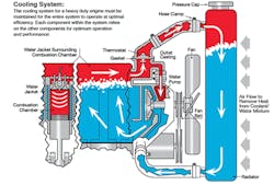
Due to the laws of thermodynamics, all engines are less than 100% efficient and produce waste heat. This unavoidable fact requires the services of an engine coolant system to remove and radiate the waste heat in an efficient and safe manner. In many ways, modern engines are victims of their own success. Modern environmental pollution control systems minimize exhaust but generate additional heat. To meet these challenges, a coolant system must provide efficient heat transfer away from the engine block to prevent engine overheat and temperature strain on the engine’s metal components. In addition to protecting the engine, a coolant system protects the liquids used in engine operation, preventing both freezing and boil over. Figure 3 shows a simplified engine coolant system.
Like the engine oil system, the coolant system relies upon a pump. In this case it is a water pump that circulates water mixed with coolant around the engine block and its combustion chambers in an open space called the water jacket. As the cool water/coolant mixture comes into contact with the hot engine, it draws off heat raising its own temperature. It then travels through a hose to a radiator located at the front of the engine. The radiator is designed with vanes that increase its surface area without increasing its overall volume. Water travelling through theses vanes sheds its excess heat with the help of a large fan or the actual movement of air through the front grill work. Heat is passed into this air flow stream and carried away from the engine.
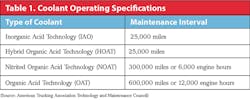
Coolants (which protect against freezing as well as overheating) come in a variety of inorganic and organic chemical formulations. These include Inorganic Additive Technology (IAT), Organic Acid Technology (OAT) formulas, and Hybrid Organic Acid Technology (HOAT). The American Trucking Associations’ Technology & Maintenance Council has established industry standards for coolant maintenance. Its recommended (“RP-365 Coolant Maintenance”) standards for each type of coolant are as shown in Table 1.
Indirectly, the coolant system must also protect itself against corrosion of all its metallic components. Since glycol and water mixtures are corrosive, inorganic and organic salts and chemicals, (corrosion inhibitors) are added to the coolant in order to prevent long-term corrosion of the cooling system components. The wrong amount or type of coolant can also cause hose cracking, breakage, and leaks. With the coolant under pressure, this can result in rapid, high-volume loss of coolant loss. Not tending to this situation immediately and responding with a quick engine shut down can result in overheating and engine breakdown. In the long term, it can cause oil breakdown and even engine deformation. Maintaining the appropriate level of coolant is essential to continued fleet operations.
Major Suppliers
Evans Cooling Systems is the nation’s only manufacturer of waterless coolants for a variety of vehicles, industrial application, gensets, and heavy-duty equipment. Waterless coolants have an advantage over traditional water based coolants, which can cause corrosion, boil over, and engine breakdowns. Waterless coolants last longer between recharges and can minimize maintenance costs. Instead of a typical 50:50 mix of ethylene glycol and water, waterless coolant is a glycol based fluid that has no need of water as an admixture (or silicates, phosphates, or supplemental coolant additives). Their “Heavy Duty Waterless Engine Coolant” has a temperature range between a freezing point of -40°F and a boiling point of 375°F. By allowing for higher operating temperatures, it increases overall fuel efficiency. It lasts the lifetime of the engine.
In addition to supplying a wide range of heavy and light equipment, John Deere also provide working fluids such as its Hy-Gard Hydraulic/Transmission Oil. It is a high-performance oil for John Deere hydraulic and transmission systems. It can work with equipment that is either equipped with common system reservoirs, or separate hydraulic systems (such as wet brakes and wet clutches). Its formula includes friction modifiers that provide smooth clutch engagement and high braking capacity with minimum chatter. Its viscosity improver additive ensures proper viscosity (between ISO grades of 46 and 68 at 104°F) at all operating temperatures exceeding industry JDM J2OC specifications.
Thunder Creek Equipment is an innovator in field services equipment. Its Service & Lube Trailer (model #SLT440, or “SLT” for short) is an affordable alternative to a lube truck, setting up like a lube truck at significantly lower costs. Each trailer is highly configurable and can be customized to meet the needs of an equipment fleet with room for up to eight tanks for oil, reclaimed oil, antifreeze, and diesel. Or, it can be equipped with an optional 100-gallon diesel exhaust fluid (DEF) and grease application systems. Its modular design allows for variable combinations 25-, 55-, and 110-gallon tanks for a combined 440 gallons. Being a customized trailer it can be hauled by any CDL driver—no need for a special HAZMAT license.
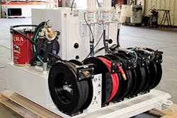
American Eagle Accessories Group is a supplier of the LubeMate brand of Mobile Lube Skid Units and Lube Trailers. The lube skids can easily be permanently mounted in service trucks, effectively turning it into a lube truck for added convenience. The Mobile option allows the user to easily load and unload the unit into the service truck for additional flexibility. Construction of the lube skids typically consist of carbon steel, however aluminum options are available on some models. The product line includes various different models of skids to fit the users needs, ranging in size from a pair of 40-gallon tanks, to one with three 100-gallon product tanks. All skid packs that have a waste oil management system include a 7.5-gallon drain pan with a quick coupler for easy disposal.