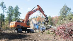
Ask contractor Van Tyler why, in one word, he likes using an ATV for site reconnaissance, and he’ll tell you why in three words: global positioning systems. It’s not the rocket science or the satellite constellations that get Tyler excited about his GPS-configured ATV; it’s the time and money that he saves. Tyler has no misunderstandings about the value of time. “When you are working on contract work,” Tyler asserts, “time is money.” He’s proud of his all-terrain-vehicle Kubota RTV-900, which he uses for layout and staking: “It has been well worth the investment because not only does it consume a fraction of the fuel that a pickup will; it can get into places better than the pickup.” Greater mobility makes the GPS-configured ATV an attractive tool indeed.
Grading & Excavation Contractor also interviewed industry leaders who have built and developed this technology, and we did so to explore its advantages and disadvantages. Alan Sharp, segment manager for site positioning with Trimble’s construction division, summarizes the benefits in this way: “A GPS-enabled ATV can be a very practical tool for contractors to get around on the job site quickly and can facilitate all phases of the construction process,” from “performing initial site measurement and verification of original ground levels” to “checking finished grade” to “carrying out as-built site measurements.” Sharp notes that “collected position data and their resulting surface models can be used to compute earthworks progress volumes, check and verify cut/fill around the job site, and set temporary grade stakes in order to keep machine operations running.”
Jason Killpack, senior product marketing manager at Topcon, takes the idea a step further, observing that a key advantage to the mobile GPS configuration is that it permits the contractor to cover vast amounts of territory. “The purpose for putting GPS on an ATV,” Killpack explains, “is to do mass measurements and grade checks over a large area. With a system on an ATV, the grade checker or superintendent can cover a large area and spot check or can continuously take measurements while covering the excavation areas to get volume calculations.”
The technology and the concepts sound complex, but they’re really rather simple, says Rich Calvird, machine control program manager for Leica Geosystems. GPS-configured ATVs offer the advantage of fast point-data collection, Calvird explains, which aids the initial reconnaissance process: “Data collected will be a compendium of discrete points for a given site, taken at set intervals.” Timers can be set up to get points every 10 to 20 feet, every five to 10 seconds, for example, or every time the elevation changes. An ATV mounted with a rover receiver is a valuable tool, Calvird argues, because of the flexibility, speed, and accuracy that it brings to the grading process.
The bottom line with this technology is that it enhances control, says Murray Lodge of Topcon. “This grade management system allows one to have better control of the everyday job site.” That’s music to the ears.
Control is a concept we all can easily grasp. When we have our control processes in order, we can feel it. It’s as if we have a sixth sense that comes into play when it comes to machine control. We understand that time is of the essence, that saving and making money gives us an edge in the market. Intuitively we know that to stay competitive in the grading and excavation game we must keep up with the latest technology. Maybe contractor Van Tyler says it best: “When I first started reading about GPS and saw how expensive it was, I kept telling myself that when those systems go to where a contractor like myself could justify the cost, then I was going to have one. When we did finally buy our first system, it was almost like getting another D-5N.” Tyler weighed the costs and benefits and determined through experience that investing in GPS doubled his production time.
Now that we know what its purpose is, how do you set up a GPS-configured ATV?
According to experts, it doesn’t require a rocket scientist or satellite engineer to sort it out. It’s all pretty basic. The nice thing is that the Big Three-Trimble, Topcon, and Leica-have made life easy for contractors by manufacturing devices that keep things simple. Alan Sharp of Trimble states that “any of the modular GPS receivers or smart GPS antennas in Trimble Site Positioning Systems portfolio can be mounted for use on an all-terrain vehicle.” These Trimble systems, Sharp highlights, are “available in a range of options to suit job-site applications, flexibility, and performance requirements.” Sharp points out that getting things right, from the beginning, is important: “Optimal setup requires a GPS receiver with integrated power and a mounting bracket, with quick disconnect for easy dismounting to support point staking applications away from the ATV.” From there, “The operator need only measure the height of the antenna from the ground,” says Sharp, “and the system is up and running.” Trimble offers the TSC2 handheld controller, which runs Trimble’s SCS900 Site Controller Software.
Topcon has developed a similar system that, like Trimble’s technology, places the GPS receiver and rod on the ATV. “Grade checkers can always see where they are on the design surface,” Killpack of Topcon says, and can have at their disposal “cut and fill information anywhere they drive the ATV on the job site.” Contractors on the front lines confirm Trimble’s and Topcon’s assertions as witness by Tyler’s eagerness to share his experiences on this point. “The big benefit of having a GPS-configured ATV,” Tyler notes, “is that the layout person can drive the vehicle almost anywhere on the job,” have a rod mounted on the ATV, and “know the distance from this rod to the ground.” The driver can move “right up to where he needs to put a stake and drop it from the bottom of this rod-it is plenty close enough,” he says, “for rough grading when we are grading for roads.”
How Do You Get the Data Out?
The purpose of GPS-configured ATVs is clear. The advantages are obvious. The setup is simple. But how do you get data out of it? Killpack explains the general principle. On the Topcon mounting system that holds the GPS receiver and rod, there is a place to attach a field collector. Data are stored inside this field collector and transferred out of the field collector via CF card, Bluetooth wireless download, or serial cable. Sharp describes the details of Trimble’s system, noting that GPS points are collected many times per second and stored on the Trimble TSC2 handheld controller or tablet computer. The newly collected data can be used in the Trimble SCS900 site controller software to “create surface models, compute volumes, and visualize cuts and fills for the site.” Data also can be synchronized from the controller in the office for later use in Trimble’s Terramodel or Business Center software. There is nothing at all new about data collection. Contractors did it long before GPS-configured ATVs ever existed. But data collection has been revolutionized by the introduction of GPS/ATV and by the software applications that transform the data into usable information. Technology literally has paved the way for more efficient and more cost-effective grading and excavation. Contractors that don’t stay informed on the latest developments won’t survive. Contractors that do keep up with technology will get more bids and make more money. “Technology does not replace people-it enables people,” says business writer Tim Richardson. “It only replaces people when they do not know how to wield it.”
Of course technology is not without its limitations. True, ATV-based GPS collection allows for more data collection at faster speeds, but are there concerns about this configuration? Trimble’s Sharp says yes. He offers a few caveats:
- Significant shock and vibration can impact precision positioning equipment if an ATV is driven fast over rough ground. “It is not uncommon for ATV-based grade checkers to abuse the equipment,” Sharp warns, “not so much while they are measuring but when they are driving fast between locations over exceedingly rough terrain.”
- Safety to operators is a more critical issue. Measuring steep slopes should be done with extreme care, Sharp cautions, or the consequences could be serious.
- Technical matters stand out in Sharp’s mind too. “Since ATV-mounted GPSs do not correct position or elevation data for pitch and roll,” he says, “the accuracy of these measurements when on slopes is not as good as measurements taken with a handheld rod taking static positions. ATV use is for speed rather than accuracy” and is used “primarily to augment machine operators, reduce staking time, and set quick, rough grade stakes to keep operations moving.”
Contractors should be aware of these caveats. They can keep their operators safe, their equipment tuned, and their slope measurements well defined. The best contractors are getting it right when it comes to site reconnaissance.
“I consider our little Kubota a piece of equipment along with the other equipment we have,” Van Tyler says. “We keep it serviced and cleaned just like we do the other pieces of equipment.” No wonder good things are happening at Van Tyler Excavating.
Triangulated Irregular Networks
What are triangulated irregular networks (TINs), and what on Earth do they have to do with site developement?
Simply put, a TIN is a mesh of non-overlapping triangles that is used to represent a surface of a construction site. The triangles are made by connecting irregularly spaced three-dimensional points. Since any triangle can represent only a single plane, an elevation for any point on the triangle can be easily interpolated from the corner elevations.
A TIN of existing elevations establishes preconstruction site conditions, while a TIN of design or proposed elevations can be used for both quantity estimating and machine control. In this regard, you might consider these two TINs as the digital go-betweens linking the initial and finished jobsite.
“Suppose we collect data about a site,” explains Rich Calvird of Leica Systems. “The points, viewed by themselves, would just be a collection of dots in space. To get a 3D map or surface model, there needs to be a way to link the points and fill in the blanks between them. The TIN file is a method for making a “˜faceted’ surface model based on taking sets of three points at a time and defining a triangle-shaped facet-so if you have a location within the three points, a fairly accurate height can be calculated.”
“The triangle mesh as a whole forms a 3D surface. The breaklines, volume boundaries, and outer boundaries force triangle sides to follow the line defined by the breakline,” adds Alan Sharp of Trimble’s construction division. “No triangle side is allowed to cross a breakline.” As a result, Sharp continues, “Breaklines effectively force creases into the surface, so that the surface is accurately represented by the minimum number of measured points.”
Sound like too much engineering information for a contractor? Not so, says Sharp. Trimble’s representative drives the point home to the job site. “The fundamental benefit of the TIN,” Sharp explains, “is that it helps contractors visually understand the data and compute volumes quickly and accurately.” Errors in collection or design can be easily identified with 3D visualization. Comparing original, design, and current surfaces allows the contractor to see and move in 3D around the model to better understand the surface, as well as the cut-and-fill requirements. “The most common application for TIN models,” Sharp notes, “is to calculate surface contours and volumes,” and volumes “can be used not only for payment purposes, but also to monitor progress and plan work.”
Establishing a TIN of Existing Site Conditions
The process of creating a TIN model of existing conditions begins by recording spot elevation data into a data collector using a total station or GPS rover. The recorded data is in relation to established control points set permanently on the site. The points contain the coordinate (usually northing, easting) and an elevation value.
How many mass points do you need? If it’s a meadow in Kansas, only a few points may fill the bill, but a washboard area north of Phoenix is liable to require intense collection. The issue here is the resolution required to provide an adequate site description. The more points you collect, the more accurate the TIN model.
Steve Warfle, product manager at InSite Software in Rush, NY, adds, “Many factors, such as topsoil stripping, demolition, type of cut material, and the quality of required fill, will affect the ultimate cost of the site development, but an accurate TIN model of existing grades is required first.”
The data provided by the engineer is often in conflict with what the contractor observes in the field, Warfle adds. “Disagreement over quantity can be caused by a variety of things, but spending the time to establish a good existing TIN model is money well spent.”
Contractors may be wary of technology because it’s not always easy to use. “Fortunately, such manufacturers as Topcon, Trimble, and Leica have recognized that interfaces to their equipment in the field have to be user friendly, and they have done a good job,” says Warfle. “Developing an accurate TIN model of the site is not difficult.”
Benefits of Good Proposed TIN Model
What’s a TIN mean for the everyday contractor during construction? Sharp opens the picture. “Using a TIN model of the design with the current XYZ position enables the user” to look at any “features of the design and know if the ground has the desired elevation or if the break in the surface is at the proper position.” Field software also enables the user to see an entire roadway cross-section relative to the position on an alignment.
Warfle gives us a way to visualize it by discussing machine control. “A machine control system,” he explains, “compares the current location of a machine blade with the desired grade at that location and either displays the difference or automatically makes a blade adjustment.” The current location of the machine is obtained either by GPS or a robotic total station. The desired grade at each location is provided by a special file containing a triangulated surface or TIN. “Unlike a staking file,” Warfle says, “a triangulated surface file contains a 3D elevation for every location on the site.”
“The 3D visualization available from the TIN model in the office,” Sharp concludes, “is in effect brought to the field so that the user can drive the design, locate the specific area of concern, compare current to specified conditions, and look at the ground to make real-time decisions.”