Introduction
Building Information Modeling (BIM) is the culmination of a millennium of human efforts to graphically represent building projects. Architects have always required graphical representation of their buildings. This technology makes these designs come alive.
A Brief History of Architectural Drawings
Humanity’s first architectural drawing will be forever unknown to us because it was literally written on sand or traced in soft mud. The oldest-known site plan is on a granite slab discovered at a 14,000-year-old archeological site in Spain. It depicts the layout of a semi-permanent campsite established by neolithic hunter-gatherers, and shows the layout of its grass huts. It predates the oldest-known images of buildings by 6,000 years.
Ancient architects achieved levels of genius in their design of Egyptian pyramids, Greek temples, and Roman palaces. But not much is known of how they drew their architectural plans. A 3,500-year design of a garden on a painted wood tablet from ancient Egypt is the oldest-known-dimensioned architectural drawing. These designs must have existed, but were probably made on perishable sheets of papyrus or paper. (Existing Roman architectural designs are either set in mosaics or carved into marble.) There is evidence that the designs were drawn directly onto the building itself as it was being constructed with its floorplan laid out directly into the ground using posts and ropes.
What we would consider to be actual design plans would have to wait until the 13th century when architects and artists (usually the same person) grasped the concept of scale and perspective. By combining the beauty of renaissance artistic genius with detailed accuracy, the earliest-known architectural plans for medieval cathedrals were works of art, compared with modern functional designs. Very few of these design plans (or portfolios) survived since they were drawn on parchment. They were either lost or destroyed, or became palimpsests as the sheets were scraped clean and reused for new text and drawings.
At the business end of medieval design, the masons performing the actual work of turning the architects’ grand design into reality would perform detailed design work in “tracing houses.” Most of this design work was devoted to ornate detail drawings created and copied by the use of “prick holes.” These served two necessary functions.
First, they defined the geometric forms of the (circles, roses, arcs, fluted columns, and such). Combining them would create more detailed designs such as a cornice or apex of a window opening.
Second, some drawings were used as master designs that additional copies were made from by pricking through their holes into the sheets underneath. This process would transfer a précis (an essential summary of the design) onto a sheet of fresh parchment.
Combined with the floorplans locating the cathedral’s interior separating walls and rooms, exterior walls, and columns and buttresses for structural support, these designs allowed for the construction of some of the most majestic buildings in history—buildings that took the use of stone to its theoretical physical limits. And still, engineering analysis was rudimentary, but not completely lacking. These designers had a lifetime of practical know how and understanding of the basic strength characteristics of their building materials (stone, marble, brick, tile, and wood). However, structural failures both during construction and even decades after completion were not uncommon. As they said back then, cathedrals were built “by guess and by God.”
The modern era of architectural design began with the invention of blueprints. Invented in the 19th century, blueprints document a design by means of a contact print process on chemical treated sheets that are sensitive to light. The light-colored lines and blue background of the blueprints make any erasing or revisions obvious, thus preserving the integrity of the document. Since the 1940s, blueprints have been replaced by whiteprints (with the opposite color scheme of blue lines and white backgrounds).
One of the best examples of the time-consuming complexity of manual architectural drawings is one of the more recent major skyscraper designs to rely on old-fashioned hand drafting. Specifically, the design and construction of One Worldwide Plaza in mid-town Manhattan (as shown in the PBS documentary series Skyscraper ) in the late ’80s. Under scheduled pressure, excavation and foundation work had already begun before the architects had completed their design. Clients and tenant were buying building space before the architects had finalized their floorplans.
A fast-track project management method presented the designers with a series of design changes requested by the building’s owner. These were mostly aesthetic changes (like brickwork on the parapet) or detail work (like seams on the roof). In fact, the design and redesign process never really stopped throughout the entire construction effort, affecting everything from the joints in the facade’s stone work, to the look of the ash trays in the elevator lobbies.
The architect’s design ideas in turn presented severe challenges to the engineers, by replacing their original rectangular steel frame core idea with one that incorporated an elliptical open lobby space on the first floor. After months of redesign and engineering analysis, a solution was created that resembled the elliptical arcade designed by the architects without cutting into the main steel columns that supported the weight of the building. The architects and engineers performed these miracles of design and scheduling—on a project so large and complicated that it was literally too big for a human mind to fully grasp on its own—largely by hand, while coordinating the activities of more than 100 companies involved in all aspects of the project.
AutoCAD Applications
And then the computer emerged, revolutionizing the field of architecture and arriving just when it was most needed. The accelerated project schedule and increased complexity experienced by One Worldwide Plaza had become a universal problem for building projects large and small. It was during the late ’80s, when One Worldwide Plaza was being designed and built that computer assisted design (CAD) really came into the market.
Invented in the ’60s, the first CAD machines (like the first computes) were large and very expensive. Only a few were sold. By the ’70s, increased computing power and reduced cost moved CAD from a curiosity to an actual design tool with widespread applications. By the end of the decade, the first true commercial CAD companies were formed. The development of three-dimensional (3D) modeling and UNIX workstations in the ’80s made CAD commercially viable. What followed was steady growth with incremental improvements in functionality, speed, and ease of use. By the end of the decade, users were ditching in-house proprietary CAD systems for commercially available software. Advances in personal computers in the years since have allowed for the use of individual workstations, personal computers, and then even laptops.
A CAD system combines computer hardware, data management, and design software to allow for electronic graphical representation of engineering and architectural design drawings. Drawings are displayed on high-quality graphics monitors and are created with a mouse (or a light pen and digitizing tablet in older models). CAD programs come with pull down menus for drawing content and style along with operator viewing aids. Each line or other drawing element is stored in the software’s database and can be used as the basis for calculating quaintest (surface area, volumes, and such). This is all accomplished with improved speed and accuracy compared to traditional manual drawings.
3D Layout Systems provide precise location reference.
But for all of its improved efficiency and accuracy, CAD by itself is just another plan drawing. BIM was needed to take it to the next level where the plans become actual simulations of the construction and functioning of the project.
BIM Methods, Capabilities, and Applications
How does BIM differ from standard AutoCAD applications? Why is it so useful? Think of it as “design plus.” It integrates architectural, engineering, and construction work tasks by utilizing a digital building model that acts as the repository of data for the building’s systems. The goal is to enhance accuracy and efficiency by improving communication between multiple parties. The result is a virtual 3D
model of a building or other development that shows all aspects of its engineering, construction, operating systems (HVAC, electrical and lighting, escalators and elevators, and such), and material takeoffs showing quantities and types of construction materials.
Not only does it illustrate the building’s finished design, it can display its construction and subsequent functioning in real time. Model displays showing its construction can display not only how the project will look at each stage of its construction, but it also shows material needs as they are needed throughout construction. BIM is not so much a drawing as it is a holographic “movie.” As such, it gives an architect and the design team a “God’s view” of the entire project. And it is this ability to make 3D models that allows designers to better visualize their project.
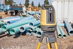
Topcon’s LN-100 Layout Navigator is designed for BIM work.
BIM is equally useful on the construction end, and it has ushered in a new era of construction management. Like similar revolutions in automation affecting manufacturing, BIM has transformed the complex process of construction project management. The result is speedier project completion and lower costs as BIM allows for true application of “just-in-time” management principles to the job site. BIM allows designers to view and update the design in 3D with each change being made immediately available to every member of the design team, the owner, contractors, and subcontractors. As each design change results in changes to material quantities, schedule, and labor allocations, it can update the entire construction effort that can be caused by the smallest structural or aesthetic design change. In doing so, it analyses the proposed change and translates it into the bottom line—the dollars and cents of the construction budget.
Major BIM Companies
Miron Construction extensively uses BIM for their design and construction processes. With a staff of full-time professionals devoted to BIM, Miron uses this system for design review, constructability review, utility modeling, O&M modeling interface, 4D time-lapsed construction, 3D animation, interference detection, cost modeling, and Leadership in Energy and Environmental Design (LEED) certification modeling.
For more than three decades, GRAPHISOFT has maintained a strong connection with research, innovation, and design and developing cutting-edge technologies that create practical solutions for architects, designers, and construction teams. These developments led to the creation of their BIM software package, ARCHICAD. This is a BIM software application used by architects, designers, engineers, and builders to professionally design, document, and collaborate on building projects. ARCHICAD is a BIM authoring tool that offers a natural and intuitive work environment, a result of the developers of the software understanding how architects think and process their designs. ARCHICAD 19 provides industry-first predictive background processing. This is an innovative solution that enables instantaneous model views and prepares anticipated actions in the background using processor cores, which would otherwise go unused.
ARCHICAD has been successfully utilized by design firms for projects across the globe. These projects include a multi-award winning college learning center in the United Kingdom, a family health and bioscience research complex in Canada, a multi-functional urban center in Russia, and a library and cultural center in Norway. These four radically different buildings are examples of the system’s flexibility and capabilities.
In addition to an aesthetically pleasing building, ARCHICAD provides the design tools to ensure sustainability, energy efficiency, and socially responsible green design—allowing architects and designers to meet these new and demanding goals. Software developed by GRAPHISOFT supports designing within some of the strictest “green certification” platforms. Users can rely on ARCHICAD and its built-in energy modeling tools to design some of the most environmentally responsible dwellings possible—passive house (Passivhaus) designed homes. At a larger scale, ARCHICAD designers can apply these same principles to designs such as the LEED-gold certified World Headquarters for the International Fund Animal Welfare. This building was designed by Boston-based firm “designLAB” in ARCHICAD integrates landscape and built form, which minimizes the negative impact of the building on its surroundings.
In short, ARCHICAD is BIM. It is a technology founded and developed on the basic principles of architecture. The software supports its users as they take buildings from conceptual design to construction—providing accurate performance data, such as structural volume, energy consumption, daylighting quality, and formal and spatial qualities.
Schindler Elevator Corporation offers elevator and escalator BIM models to assist architects during the building design phase. These 3D scale models let architects compare capacities, door opening and travel options, and allow them to see how an elevator or escalator will fit into their building plans. Incorporating these models during the early stages of planning helps prevent pitfalls later in the process, such as space conflicts, design and operational limitations, and incompatible layouts and usage.
Turner Construction Company uses BIM in the field to create a “smart job site.” By working with designers, subcontractors, and owners from the start of the design phase, Turner can leverage the use of BIM to identify risk on the job.
These onsite BIM applications include 3D virtual trade coordination, estimating, scheduling, constructability reviews, and logistics planning. BIM combined with laser scanning can be used to capture existing conditions accurately and efficiently, producing a model based representation for the design team. In doing so Turner can work with designers to identify variances from as-built documentation and deficiencies in surfaces not being level or plumb due to settlement or improper placement.
Utilizing Visual Production Control Turner captures job site material information from multiple sources and improves supply chain management. These information sources can include Radio Frequency Identification (RFID) tags and barcodes allowing for rapid project status updates and on time delivery of materials. With this information an owner can quickly ascertain which materials are onsite, in place, or not yet installed. This accurate and up to date record keeping can be used to identify issues with supply lines or rapidly adjust the project schedule.
Turner also uses BIM technology to ensure building quality with Model-Based Layout with Robotic Total Stations. Using this technique, Turner can take standard survey methods and augment them with precise location coordinates from the model. This 3D model-based coordination process improves trade coordination and the accuracy of building layout in the field, while saving manpower and time. It can even allow for the offsite construction prefabrication of systems and assemblies, resulting in a wider variety of customized building systems and improved construction safety.
Trimble’s 3D Laser Scanning solutions provide as built collection of existing conditions for renovation projects, as well as progressive project data collection for QA/QC purposes. It is fully integrated with collaborative software from Tekla (a Trimble company), such as Tekla BIMsight, a professional tool for construction project collaboration. With these tools, a construction work force can coordinate and combine their various 3D design models, check for conflicts between them, and share information between each other in a BIM operating environment. Together, they can construct a virtual world simulating a building that includes all trades, disciplines, and operating systems before construction actually begins.
This last capability allows for easy coordination of mechanical, electrical, and plumbing (MEP) contractors and their design teams. Together, they can layout out complicated electrical, mechanical, and HVAC systems in a timely manner. Tekla BIMsight can also import other design extensions including DWG, DXF, DGN, and IFC.
Autodesk’s BIM 360 family of software applications allows remote access to project data throughout a building’s preconstruction design effort and construction life cycle. BIM 360 Glue is a cloud-based BIM management and collaboration product that connects project teams and helps streamline BIM project workflows. This allows for timely resolution of field conflicts and coordination issues.
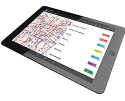
Its companion software, BIM 360 Docs, is a Web service that ensures that every member of the project team is working with the correct and up-to-date versions of the building’s design. It delivers complete and connect solution for managing 2D designs and 3D models. These documents can be viewed in thumbnail, list, and registry modes. The third member of the BIM 360 family is their BIM 360 Field. Use for managing field operations and processes (quality, safety, scheduling, and commissioning) via cloud-based collaboration and reporting for onsite use via mobile devices.
InSite’s Sitework Earthwork and Utility Estimating Software combined with their Field General GPS Modeling software allows for the preparation of point data for site layout while utilizing traditional data collectors and standard positioning equipment (two-person station, robotic station, GPS, etc.).
In addition to allowing an operator to fine tune machine control models (and export this information to any brand of machine control system) Field General allows for easy preparation of staking files. By just picking points from a CAD file, indicating the offset distance and the frequency interval of staking the system can greatly simplify the task of offset staking of curbs, buildings, roads, and such. The operator can even dual offset the centerline of a proposed road alignment, get intermediate stake elevations between designed points, and print a scaled layout plan. Armed with this data, an operator can use its BIM capabilities to measure work in progress and verify work done to date.
Survey “as-built” data shot from the site can be imported as an alternate set of grades and InSite will instantly calculate volume numbers. This can be done sequentially for each phase of construction and having InSite calculate a new round of quantities. Graphical capabilities allow the operator to display these surfaces in cross sections, 3D displays, and cut-and-fill maps.
Triangulated design surfaces (aka .tin files) can also be exported to machine control to various products (Caterpillar Accugrade, Leica PowerGrade 3D systems, Topcon’s 3DMC2 and Trimble’s Grade Control System, etc.). Working with the GPS unit to provide northing and easting locations, the InSite triangulated surfaces provide exact 3D point locations to guide the equipment blade or bucket. Finally, their 3D Live system allows an operator to view the 3D in real time as data is entered and edited to speed up the take-off process and model building.
Roctek International Corp.’s SOFTScale and SOFTScale LT provides its users with the ability to perform accurate and easy structural takeoffs from paper or digital plans such as PDFs, DXF, or DWG files (from BIM compliant 3D models). These models show exact material quantities in 3D graphics. A layered application, it provides 3D views of all takeoff measurements. With a single click, an operator can transfer quantity totals to an Excel (or Lotus work) sheet or to any other construction industry-specific estimating application into which quantities can be transferred easily.
Accurate data can be entered either by a digitizer or directly on the screen (with the ability to switch seamlessly between the two modes on the same job) by these system and can provide accurate quantities from AutoCAD, PDF, BMP, Tiff, JPG, and other file types. The operator can create analytical formulas for estimating complicated takeoffs from roofs, slabs, ceiling and floor tiles, columns, and other specialty components. SOFTScale includes advanced measurements such as masonry and concrete walls (both retaining walls and foundations), concrete slabs, roofs and roofing materials, flooring (both carpets and tiles), footings, lumber frames and walls, and other types of estimates. In addition to providing operators with customized calculated quantities its custom measurement function allows for estimating unit and total costs.
Topcon Positioning Systems’ LN-100 layout navigator is a tool dedicated to BIM layout work. It combines established Topcon laser and robotic total station technologies. The operator simply needs a prism pole and a touch screen field controller to perform the 3D layout task. There the operator can take control by using either Topcon’s Android platform app of MAGNET Construct, Windows-based MAGNET Field Layout or Autodesk’s BIM 360 Layout controller software anywhere in the work site’s layout zone to get precise horizontal dimensions and vertical elevations. The LN-100 can be mounted as needed with Topcon’s additional accessories. This fusion of laser and robotic technologies combines to deliver a self-leveling design layout solution for the modern job site.
Viewpoint Construction Software provides a fully integrated suite of software tools with Vista that allows for efficient synchronization of all aspects of the construction business. Vista includes solutions for Accounting/HR, Project Management, Project Collaboration, Mobile, Estimating, Content Management, and Service Management. Viewpoint For Projects is a configurable cloud-based document control solution used to manage all construction documents, such as drawings, submittals, contracts, photos and (building information) models.
The solution helps improve the coordination and collaboration between all members of a project team (owner, architect, construction manager, engineers, and subcontractors), by leveraging project information found in Vista and publishing documents directly into Viewpoint For Projects. Field teams utilize mobile and BIM capabilities, providing a direct connection to project information wherever they are located. Viewpoint For Field View is powerful cloud-based and mobile solution that allows contractors to capture field reports and information from anywhere—even without an Internet connection—helping resolve issues quickly, eliminate paper, reduce risk, and deliver higher-quality projects.


