Movement causes friction. Friction causes heat and wearing away of surfaces in contact. Both lead to mechanical failure and physical breakdown of the objects in motion. In this case, the objects in question are machine parts of heavy equipment (dozers, graders, loaders, excavators, trucks, etc.), their engines, drive trains, and hydraulic systems. As such, this equipment utilizes large quantities of oil, transmission fluid, lubricants, and hydraulic fluid. The operators need to perform standard maintenance on these systems like ensuring that the required amount of fluid is maintained, as well as the performance of repairs such as plugging leaks and replacing worn-out parts.
But there is an added dimension to the care of this machinery that revolves around the harsh conditions encountered during winter months and episodes of extremely cold temperatures. Special applications and maintenance routines are required even if the equipment is stored away until the start of next year’s construction season. These procedures become doubly important when these machines are used in adverse winter conditions. These all require winter weather hacks to ensure proper operation and long operating lifetimes while minimizing overall ownership costs.
Engine Oil—The Basics
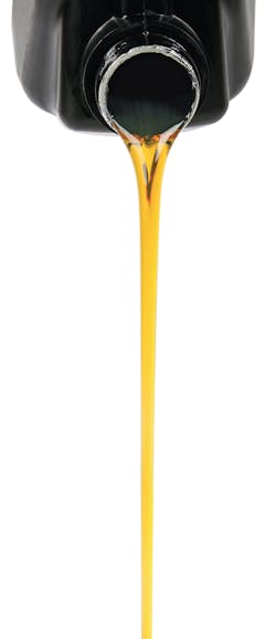
The first and perhaps most important fluid system for heavy machinery is engine oil. The job of engine oil is to lubricate the bearings of the piston pin and the walls of the piston cylinder. These all get a coating of oil to lubricate the motion of the enclosed piston while the piston is moving. Maintaining a proper thickness of oil over all contact surfaces prevents physical contact. Oil also absorbs heat from the engine and its moving parts. The oil transfers this heat to the oil sump as it cycles through the engine, which prevents the engine from overheating. Oil also cushions the engine against the sudden application of heavier loads and increased torque. Oil seals off and fills open spaces which prevents gas being blown out from the pistons. Oil is fed to each piston in the engine block through branch feeder tubes from the main engine oil pipeline. Similar branch tubes deliver oil to gears, timing chain, and the drive/camshaft.
Used oil is continuously replaced by fresh oil, with the oil draining back to the oil sump that holds the engine’s reserve of oil. The oil sump often encloses the entire lower portion of the engine block to ensure complete capture of the used oil. The whole system is a series of interconnected tubes and pipelines that allow for this constant circular flow of oil. The start and endpoint of each drop of oil is the aforementioned oil sump. From there it circulates to where it is needed on the engine’s moving parts at the required temperature, pressure, and flow rate. Therefore, the oil circulation system relies on pumps to provide the necessary pressure, cooling structures to reduce temperature and prevent the oil from overheating, and a filter system to remove accumulated impurities.
Oil sump pumps are at the heart of the system. These have to be both sophisticated in design and ruggedly durable. It is typically a gear-type pump; enmeshed rotating gears “pinch” the oil that fills the space between the gear teeth forward into the discharge tubes. Continuous spinning pushes the oil under pressure down the discharge tube and into the engine oil distribution system.
Another key component of this system is the oil filter, which is typically the first component that the pumped oil enters. The filter traps impurities that could harm the engine bearings or piston heads or clog up fuel injection ports. Rock, dust, dirt, sand, and water working their way into engine components will form an abrasive that will significantly reduce bearing life. The retained dirt particles and other impurities remained trapped within the layers of the filter until the filter unit itself is replaced. This is performed as part of the vehicle or equipment’s regular maintenance cycle, which in turn depends on hours of operation. The circulation of oil through an engine effectively keeps it clean.
The main work is performed in what is referred to as the oil gallery. This is a series of discharge tubes from the pump and filter connecting the oil supply to the engine’s main bearings via drilled holes in the engine block. An oil pressure gauge is installed on the main discharge tube to ensure a constant flow of oil and also to ensure that the minimum pressure needed to force the oil through the filter and around the fittings and bearings is maintained. From the bearings, oil is pumped once again through drilled holes to the crankshaft to ensure proper lubrication for the pistons, bearings, linkages, and connection rods (some of which are designed with grooves and holes that retain oil).
Oil completing its cycle through a hot running engine becomes very hot itself as it absorbs heat from ignition and friction. Once it returns to the sump pump, it is allowed to cool. The sump acts as a cooler in addition to serving as a reservoir for the oil. The heat from the stored oil is carried away by engine coolant circulating the sump in tubes that carry the heated coolant to the radiator to expel the heat. In addition to heat carried off by the coolant, direct radiation of heat takes place through the walls of the sump. From there, it is directly radiated to the surrounding air, further cooling the oil back down to a usable temperature.
Severe consequences occur if the oil system is not properly maintained. Moving parts get worn out and deformed, especially the crankshaft. This deformation can reduce the engine pressure and cause the oil to be thrown all over the inside of the engine. As a result, the engine will burn oil instead of circulating it. This causes a negative feedback loop: as more oil gets burned, the engine runs hotter which causes further deformation which causes more oil to be burned. Pistons can also deform, preventing the piston rings from containing the oil splash which further increases the effects of the negative feedback loop. Additionally, seals are weakened, allowing the leakage of the fuel/air mixture from the piston heads. And even with the most stringent maintenance procedure, even the best oil degrades chemically and physically over time. This requires regular and vigilant oil changes where old, worn-out oil is replaced with new oil.
Lube, Undercarriage, and Wheel Bearings
People often confuse lube and oil, treating them as the same thing. But they serve two different functions. Lube jobs involve the application of oil and lubricant to exterior parts of the engine and vehicles: the suspension system, drivelines, and the vehicle chassis. None of these parts are connected to the oil circulation system, nor do they share oil with the engine’s oil system. Instead, the focus of a lube job is the undercarriage to minimize wear and tear while ensuring freedom of movement for all of the linked and moving parts of the undercarriage.
Some equipment and truck operations ensure proper oil and lubrication with the use of an automatic lubrication system as opposed to manual lube applications. To complete a lube job for heavy equipment or trucks usually requires at least a half an hour to over an hour every workday. In addition to the safety issues posed by performing lube jobs in the field, and delays caused by bad weather, this process can result in loss of vehicle productivity and diversion of labor resources away from the actual project. An additional piece of equipment, the lube truck, is needed to follow around the equipment fleet while it is working and may not be available when needed, leading to further unproductive downtime. Workers skilled in the performance of lube jobs are becoming fewer and pose a labor shortage problem (or additional costs for training) to equipment owners.
Standard automatic lubrication systems include electric pumps, flow meters, control valves, supply hoses with branch feedlines, a lubricant storage reservoir, and malfunction warning systems. Grease flow is controlled by divider valves which move flows to where they are needed, applying the required amounts at each pin or bearing location. The extent of the lube application is controlled by proximity switches which indicate that the lube application is complete and signal the pump to shut off.
Hydraulics Systems
Earthmoving equipment exerts massive amounts of force, and hydraulic systems are force multipliers. Using a principle known to the ancient Greeks, an incompressible fluid (such as oil) transmits pressure applied at one end to another end without loss. That is, the pressure gets directly transferred to the operating end of the system as the pressure stays constant throughout the fluid. Furthermore, constant pressure can increase force.
For example, 100 pounds of force applied on a fluid in a pipeline 1 square inch in cross-section area is subject to a pressure of 100 psi. Should the receiving end of this fluid have a cross-sectional or contact area of 10 square inches, the resultant applied force is 1,000 pounds (100 psi x 10 square inches). A price is paid in movement as the distance moved by the receiving end is proportional to the ratio between the cross-sectional areas. In this case, the distance that the surface moved is reduced by 1/10. So, if the applied load (like a hydraulic piston) moves 10 feet, the receiving surface only moves 1 foot.
For most hydraulic systems, there is a master cylinder that applies the loads, and since incompressible fluid does not lose pressure, a complicated series of pipelines, hoses, valves, and connections is all connected to the main cylinder that can be used to operate many mechanisms and lift multiple loads. These tubes are connected to a series of slave cylinders that operate machine arms, cranes, levers, etc. with increased force.
In any case, the hydraulic fluid used to transmit the force cannot be allowed to leak, requiring all tubes, fitting, and cylinders to be properly sealed even while subject to high operating pressures. In addition to allowing the escape of hydraulic fluid, leaks can allow air to enter the service lines and cylinders. The air bubbles that form can cause the system to feel “mushy” since, unlike hydraulic fluid, air is compressible. Seals on appurtenances, fitting, and cylinders must be very strong and durable, able to withstand pressures as high as 50,000 psi. Only certain materials, such as titanium, steel, and stainless steel alloys, brass, woven wire, and synthetics are strong enough to provide secure sealing. Titanium is often used in extreme high-pressure systems operating at more than 50,000 psi.
Like oil, hydraulic systems utilize pumps. However, instead of using pumps for circulation, hydraulic pumps are used to apply pressure to the system. Also, to be powerful enough to provide the needed pressure, the pump must be able to handle the types of chemicals used as hydraulic fluids (mineral oil, polyalphaolefin, or organophosphate ester). Like engine oil, hydraulic fluid also passes through a filter to remove impurities.
Each earthmoving machine has a different number and variety of actuators and slave cylinders depending on its designed loading capacity and overall complexity. Crawler excavators need at least a half dozen actuators, one each for the boom, lift arm, swing pivot, bucket, travel left, and travel right (for each tractor tread). Simpler skid loaders only require three, one each for raising and lowering the bucket, vertically tilting and rotating the bucket, and a combination of vertically tilting and rotating the bucket to split it in two and allow it to grab large objects. Simplest of all are the dump trucks that have at most two actuators to raise and lower their beds. The more complicated systems may require all of the actuators to operate to do a combination of these movements simultaneously.
Winterizing Your Equipment and Fluid Systems
So, how are the above operations performed during the standard construction season with its comfortable to hot temperatures when the mercury falls below 32°F?
Hydraulic fluid with a lighter viscosity is needed in extreme cold working conditions. Note that the viscosity of hydraulic fluids (as well as engine oil) is rated in relation to the system’s pump system. Viscosity is a fluid’s internal resistance to flow and shear. It is usually rated for operational temperatures between 40°C (104°F) to 100°C (212°F). Viscosity is measured in centistokes(1 square millimeter per second). Industry standards rate hydraulic fluids by viscosity standards as designated by their ISO number or grading (ISO VG 32, 46, and 68). The standard viscosity range for a hydraulic fluid at its highest operating efficiency for most applications is between 10 and 100 centistokes.
Picking the wrong hydraulic fluid can result in mechanical stress on the pump or even pump failure. Thicker fluids (tars, syrups, etc.) have higher viscosity while thinner fluids (water, light oils, etc.) have lower viscosity. Even under normal operating conditions, the viscosity of a hydraulic fluid is critical to its importance, efficiency, and long-term wear and tear on valves, cylinders, and pumps. Hydrocarbon fluids are long-chained molecules with the longer-chained molecules having higher viscosity. And while synthetic hydraulic fluids can have molecular structures tailored to the application, all hydraulic fluids tend to break down over time and experience reduced viscosity.
The same cold weather issues that affect hydraulic fluids also affect engine oil. Colder weather increases the viscosity of the engine oil. As a result, the flow of oil is reduced and the oil pump has to work harder. Thicker oil is harder to push through an oil filter and takes longer to circulate through the engine block. As a result, engine heat is not dissipated effectively, and damage from friction can increase. Cold engine oil, therefore, results in lower fuel efficiency. But the worst-case scenario is possible damage to the engine itself as the oil simply does not perform as needed.
Not mentioned above are two other fluids, the gasoline or diesel fuel that powers the engine and coolant that regulates its operating temperature. In extremely cold weather conditions, an anti-gel agent is often added to the fuel mix. This helps to stabilize the fuel during very cold operating conditions. Both fuel lines and fuel filters tend to be exposed outside of the main engine body, making them more susceptible to the effects of the cold. These anti-gel agents prevent fuel in exposed fuel lines from icing up and also prevent ice formation in fuel filters. Gasoline and diesel reserve stored in aboveground tanks, barrels, or canisters can also suffer the effects of extreme cold, so it is best to add an anti-gel agent to fuel reserves as well. Another old trick is to top off the gas tank during winter to prevent the formation of condensate and then ice within the gas tank.
Equipment not used during winter months has to be prepared for storage until the start of the next construction season. The first step is a thorough inspection of the machine as a whole and all of its important moving parts (including door hinges). This visual inspection should look for any worn parts. Following this, a complete lube job should be performed to lubricate joints and seal areas where ice may intrude. Here, the right choice is a thicker, high-viscosity lube that won’t drip off the equipment and maintains a complete coverage for the winter. Next, the oil should be completely changed and replaced with winter-grade engine oil along with a new oil filter. Antifreeze should be added to the engine coolant system following the manufacturer’s requirements and specifications. As the engine sits cold and idle over the winter, the antifreeze will prevent ice buildup and potential damage to the engine. Lastly, extract the last of the diesel from the fuel tank, remove any attachments such as buckets and blades, and store the battery in a room-temperature facility. Keep a record of when the equipment was stored, throw a tarp over it, and secure it for winter storage.
While focusing on the mechanical aspects of winter operations, the human element should not be ignored. Maintenance crews need to be well versed on the more extensive maintenance schedules and associated safety problems that come with cold weather. Operators need to be trained in moving and working their equipment in potentially adverse ground conditions and being cognizant of the proper cold weather operating parameters for their equipment.
Major Suppliers
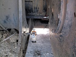
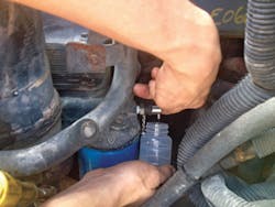
The sampling and testing of engine oil and hydraulics fluids is a much-needed service that needs to be done with precision. Samples need to be reliable and data-rich for the analysis to be beneficial. Checkfluid provides a much-needed service to make sure your samples are just that. They manufacture specialized sampling valves for engines, hydraulics, and final drive systems. Their most popular valve is the KP Pushbutton. The name says it all: it is a push-to-sample valve that will allow you to sample your systems without shutting down. Simply press the button to activate, and once released, the valve closes automatically. Commonly installed on engines and hydraulic systems, it reduces the risk of cross-contamination and the inaccuracies of sampling right from the drain pan. Sampling at idle with pressures up to 750 psi, it can be installed on systems with pressures as high as 6,000 psi.
CASE Construction provides specialty equipment for a task similar to that of earthmoving: snow removal. CASE is specially designed for the task of snow removal, allowing operators to complete jobs faster, cleaner, and with lower operating costs. Rugged CASE snow removal equipment can power through deep snowdrifts or piles of previously removed snow that need loading onto trucks for offsite removal. Its design allows for easy maneuvering into hard-to-reach places that trucks and plows cannot access. With any of their other 250-plus attachments, this equipment can perform tasks in any season. These include the CASE G Series wheel loaders, Case F series compact wheel loaders, and the CASE skid-steer and compact track loaders.


